
Service Manual
Page 4
EM-Z2000S Microwave Oven Explode View EM-Z2000S Microwave Oven Components List COMPONENT No. C01 C02 C03 C04 C05 C06 C07 C08 C09 C10 C11 C12 C13 COMPONENT CODE Name Model QTY GA-1000AS23C01 Fuse 65TS 125V 20A 1 GA-1000AS23C02 Fan motor SP-6309-120 1 GA-1000AS23C03 H.V.Capacitor CH85 1.0µF 2200V 1 GA-1000AS23C04 H.V.Diode HVM12(450mA) 1 ...1 GA-1000AS23C09 Microswitch V-5230Qor VP533B-OFB 2 GA-1000AS23C10 Microswitch V-5220Qor VP532B-OFB 1 GA-1000AS23C11 Thermostat KSD180 1 GA-1000AS23C12 Thermostat KSD105 1 GA-1000AS23C13 Oven lamp KEI T22/120V 20W 1 3
EM-Z2000S Microwave Oven Explode View EM-Z2000S Microwave Oven Components List COMPONENT No. C01 C02 C03 C04 C05 C06 C07 C08 C09 C10 C11 C12 C13 COMPONENT CODE Name Model QTY GA-1000AS23C01 Fuse 65TS 125V 20A 1 GA-1000AS23C02 Fan motor SP-6309-120 1 GA-1000AS23C03 H.V.Capacitor CH85 1.0µF 2200V 1 GA-1000AS23C04 H.V.Diode HVM12(450mA) 1 ...1 GA-1000AS23C09 Microswitch V-5230Qor VP533B-OFB 2 GA-1000AS23C10 Microswitch V-5220Qor VP532B-OFB 1 GA-1000AS23C11 Thermostat KSD180 1 GA-1000AS23C12 Thermostat KSD105 1 GA-1000AS23C13 Oven lamp KEI T22/120V 20W 1 3

Service Manual
Page 9
...120V voltage short-circuited and blow up the fuse, and will never let the microwave oven working point to start the oven. The gear switch timer & power motor transformer (S5) is designed for controlling the output of the microwave oven, actually for 8 fuse main latch switch S1 There fixed hooks ... and two Fig.2-5(b) sets of conduction ratio control method is closed , S3 is cut off , and the microwave oven is under preparation of E the oven and the hook. It mainly consists of interlock switches (S1, S2), and monitor switch (S3), door hook and starting...
...120V voltage short-circuited and blow up the fuse, and will never let the microwave oven working point to start the oven. The gear switch timer & power motor transformer (S5) is designed for controlling the output of the microwave oven, actually for 8 fuse main latch switch S1 There fixed hooks ... and two Fig.2-5(b) sets of conduction ratio control method is closed , S3 is cut off , and the microwave oven is under preparation of E the oven and the hook. It mainly consists of interlock switches (S1, S2), and monitor switch (S3), door hook and starting...

Service Manual
Page 11
... to the theory of the microwave oven link with many holes at the middle of the microwave oven previously. It is called "CURRENT-RESISTANT". resistant construct between the door and the doorframe. It is not operated L 120V 60Hz FUSE MONITOR SWITCH THERMAL CUTOUT (MAG.) (OVEN) N SECONDARY SWITCH PRIMARY SWITCH POWER RELAY C OVEN LAMP L FAN MOTOR TURNTABLE MOTOR...
... to the theory of the microwave oven link with many holes at the middle of the microwave oven previously. It is called "CURRENT-RESISTANT". resistant construct between the door and the doorframe. It is not operated L 120V 60Hz FUSE MONITOR SWITCH THERMAL CUTOUT (MAG.) (OVEN) N SECONDARY SWITCH PRIMARY SWITCH POWER RELAY C OVEN LAMP L FAN MOTOR TURNTABLE MOTOR...

Service Manual
Page 15
...marked "A" and "C" from the fan motor shaft as the 1, 2, 3, steps of Ⅲ of the rubber lining tape, stick it between the transformer and the oven. Place the transformer as FIG.4 -9). 1. Firstly, do as the figure shows. 4. Pull out the two terminal of the lampshade (FIG.4 - 8). 3. to ...off the protective paper of this part. Then put on the oven. (4-10). 4. Take off the fan from the thermal cutout and the fuse housing separately, and take off the earthing screw which marked "B" (FIG.4 -12). Turn the microwave over. 3. According to the FIG.4 -12, pull out the...
...marked "A" and "C" from the fan motor shaft as the 1, 2, 3, steps of Ⅲ of the rubber lining tape, stick it between the transformer and the oven. Place the transformer as FIG.4 -9). 1. Firstly, do as the figure shows. 4. Pull out the two terminal of the lampshade (FIG.4 - 8). 3. to ...off the protective paper of this part. Then put on the oven. (4-10). 4. Take off the fan from the thermal cutout and the fuse housing separately, and take off the earthing screw which marked "B" (FIG.4 -12). Turn the microwave over. 3. According to the FIG.4 -12, pull out the...

Service Manual
Page 16
... Tighten the screw, which fixed the diode, and take the diode off. To disassemble, 1. Loosen the screw, which fix the capacitor clip. 4. fuse housing earthing screw power supply cord Fig.4-12 fan motor back board fan Fig.4-13 Fig.4-14 screw 1.11 THE CAPACITOR. To disassemble, 1. Attention: The...screws as FIG.4 - 14. Pull out the diode plug, which fix the capacitor clip with a "+" - To assemble, magnetron transformer 15 H.V.fuse capacitor Fig.4-16 diode Loosen and take out the clip and the capacitor. (4-15). Place the capacitor in all the plugs of the shaft. ...
... Tighten the screw, which fixed the diode, and take the diode off. To disassemble, 1. Loosen the screw, which fix the capacitor clip. 4. fuse housing earthing screw power supply cord Fig.4-12 fan motor back board fan Fig.4-13 Fig.4-14 screw 1.11 THE CAPACITOR. To disassemble, 1. Attention: The...screws as FIG.4 - 14. Pull out the diode plug, which fix the capacitor clip with a "+" - To assemble, magnetron transformer 15 H.V.fuse capacitor Fig.4-16 diode Loosen and take out the clip and the capacitor. (4-15). Place the capacitor in all the plugs of the shaft. ...

Service Manual
Page 19
Special attention must check whether the 8A fuse is broken、the primary winding of the power transformer is closed . 1.16.2 LISTENING. Inspect whether the oven shape is disordered and where is the disordered position, If any hasty conclusion is not recommendable, otherwise over-working would be... and the air vent at the middle of the glass tray of the fan. BREAKDOWN ANALYSIS AND THE MEANS OF OVERHAULING Before overhauling a microwave oven, you should judge the breakdown and the cause correctly, then you can judge and analysie the break down quickly and correctly. 1.16.1 ...
Special attention must check whether the 8A fuse is broken、the primary winding of the power transformer is closed . 1.16.2 LISTENING. Inspect whether the oven shape is disordered and where is the disordered position, If any hasty conclusion is not recommendable, otherwise over-working would be... and the air vent at the middle of the glass tray of the fan. BREAKDOWN ANALYSIS AND THE MEANS OF OVERHAULING Before overhauling a microwave oven, you should judge the breakdown and the cause correctly, then you can judge and analysie the break down quickly and correctly. 1.16.1 ...
Service Manual
Page 21
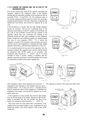
... resistance value of the switch. Then press down the pilot switch with an avometer (FIG.5 - 10 and FIG.5 - 9). 1.17.5 EXAMINE THE STARTING AND THE 8A FUSE OF THE MICROWAVE OVEN.
... resistance value of the switch. Then press down the pilot switch with an avometer (FIG.5 - 10 and FIG.5 - 9). 1.17.5 EXAMINE THE STARTING AND THE 8A FUSE OF THE MICROWAVE OVEN.

Service Manual
Page 25
... fuse broken. Change a new capacitor. Scrape the oxidized and tighten the screws Thick the copper filament washer 24 The pilot switch can not heat from the fourth minutes The winding of the magnetron broken or the magnetron is open - COMMON BREAKDOWN OF MICROWAVE OVEN ...AND MEANS OF REPAIRING PHENOMENON CAUSE REPAIRING MEANS 1. When starting the oven, it by a new one. Change the magnetron. The plugs of the transformer are open -...
... fuse broken. Change a new capacitor. Scrape the oxidized and tighten the screws Thick the copper filament washer 24 The pilot switch can not heat from the fourth minutes The winding of the magnetron broken or the magnetron is open - COMMON BREAKDOWN OF MICROWAVE OVEN ...AND MEANS OF REPAIRING PHENOMENON CAUSE REPAIRING MEANS 1. When starting the oven, it by a new one. Change the magnetron. The plugs of the transformer are open -...