English Manual
Page 12
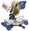
... the upper blade guard as the saw is inoperable. diameter may be used. Store the padlock key in the switch trigger. When the lock is installed and locked, the switch is lowered into the workpiece. SELF-RETRACTING LOWER BLADE GUARD The lower blade guard is made of ...shock-resistant, seethrough plastic that provides protection from the power supply and lock the switch in . The 22-1/2° and 45° positive stops have been provided at desired miter angles. SWITCH TRIGGER See Figure 4. To prevent unauthorized use of the compound miter saw...
... the upper blade guard as the saw is inoperable. diameter may be used. Store the padlock key in the switch trigger. When the lock is installed and locked, the switch is lowered into the workpiece. SELF-RETRACTING LOWER BLADE GUARD The lower blade guard is made of ...shock-resistant, seethrough plastic that provides protection from the power supply and lock the switch in . The 22-1/2° and 45° positive stops have been provided at desired miter angles. SWITCH TRIGGER See Figure 4. To prevent unauthorized use of the compound miter saw...
English Manual
Page 15
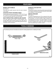
... workpiece to beginning any clamp with the operation of serious personal injury. Always make sure there is no interference with the blade guard prior to the fence or the saw table. Miter Lock Handle To Tighten To Loosen dust bag exhaust port Fig. 8 Fig. 9 Base 15 Work Clamp Fig. ...the two metal clips to heed this warning can result in between the grooves on the exhaust port. A dust bag is very helpful when cutting compound miters. Release the clips. WORK CLAMP See Figure 10. To install the work clamp: Place the shaft of the workpiece, it on...
... workpiece to beginning any clamp with the operation of serious personal injury. Always make sure there is no interference with the blade guard prior to the fence or the saw table. Miter Lock Handle To Tighten To Loosen dust bag exhaust port Fig. 8 Fig. 9 Base 15 Work Clamp Fig. ...the two metal clips to heed this warning can result in between the grooves on the exhaust port. A dust bag is very helpful when cutting compound miters. Release the clips. WORK CLAMP See Figure 10. To install the work clamp: Place the shaft of the workpiece, it on...
English Manual
Page 18
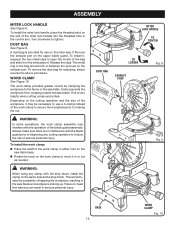
...square and throat plate are needed. Using the blade wrench provided, loosen the socket head screws securing the fence. Never operate the saw without all guards securely in place and in the illustrations. Place the other leg of the square against the fence. This is positioned at 0°. ...the fence left or right until the pointer on the control arm is intentional so that we can clearly show only portions of the compound miter saw arm to its full raised position. Loosen the miter lock handle approximately one leg of the square beside the throat plate in...
...square and throat plate are needed. Using the blade wrench provided, loosen the socket head screws securing the fence. Never operate the saw without all guards securely in place and in the illustrations. Place the other leg of the square against the fence. This is positioned at 0°. ...the fence left or right until the pointer on the control arm is intentional so that we can clearly show only portions of the compound miter saw arm to its full raised position. Loosen the miter lock handle approximately one leg of the square beside the throat plate in...
Repair Sheet
Page 3
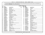
MODEL NUMBER TS1342L The model number will be found on a...mm, Pan Hd 1 * Screw (M5 x 10 mm, Pan Hd 4 Data Label 1 Upper Blade Guard Assembly (Inc. RYOBI 10 in all correspondence regarding your MITER SAW or when ordering repair parts. Parallel Key 1 Lock Ring 1 Gear 1 C-Ring 1 Ball Bearing (6000ZZ...15 mm, Pan Hd 1 Warning Label 1 Warning Label (Upper Guard 1 Logo Label (Upper Guard 1 * Screw 1 Dust Bag 1 Motor Housing Assembly (Inc. Key Nos. 1-13 and 15-22 1 * Standard Hardware Item - NO. COMPOUND MITER SAW - NUMBER 1 089100212007 2 588004100 3 A19003050302 4 580309000 5 ...
MODEL NUMBER TS1342L The model number will be found on a...mm, Pan Hd 1 * Screw (M5 x 10 mm, Pan Hd 4 Data Label 1 Upper Blade Guard Assembly (Inc. RYOBI 10 in all correspondence regarding your MITER SAW or when ordering repair parts. Parallel Key 1 Lock Ring 1 Gear 1 C-Ring 1 Ball Bearing (6000ZZ...15 mm, Pan Hd 1 Warning Label 1 Warning Label (Upper Guard 1 Logo Label (Upper Guard 1 * Screw 1 Dust Bag 1 Motor Housing Assembly (Inc. Key Nos. 1-13 and 15-22 1 * Standard Hardware Item - NO. COMPOUND MITER SAW - NUMBER 1 089100212007 2 588004100 3 A19003050302 4 580309000 5 ...
Repair Sheet
Page 5
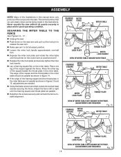
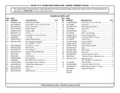
... 089100207030 figure B PARTS LIST DESCRIPTION QTY. MODEL NUMBER TS1342L The model number will be found on a plate attached... 518106300 Throat Plate (Table Insert 1 43 A07003100256 Miter Table 1 44 089100207113 Fence 1 987000329 Safety Guard 1 8-05-08 (Rev:01) DESCRIPTION QTY. * Screw (M4 x 9 mm, Pan Hd... "No Hands Zone" Label 2 "No Hands Zone" Boundary Line 2 Base Assembly (Inc. COMPOUND MITER SAW - Always mention the model number in . Hd 4 25 503118000 Bevel Lock Knob 1 26 ...RYOBI 10 in all correspondence regarding your MITER SAW or when ordering repair parts.
... 089100207030 figure B PARTS LIST DESCRIPTION QTY. MODEL NUMBER TS1342L The model number will be found on a plate attached... 518106300 Throat Plate (Table Insert 1 43 A07003100256 Miter Table 1 44 089100207113 Fence 1 987000329 Safety Guard 1 8-05-08 (Rev:01) DESCRIPTION QTY. * Screw (M4 x 9 mm, Pan Hd... "No Hands Zone" Label 2 "No Hands Zone" Boundary Line 2 Base Assembly (Inc. COMPOUND MITER SAW - Always mention the model number in . Hd 4 25 503118000 Bevel Lock Knob 1 26 ...RYOBI 10 in all correspondence regarding your MITER SAW or when ordering repair parts.


