User Manual
Page 3
...WORK. Feed work when practical. Failure to this tool. GUARD AGAINST ELECTRICAL SHOCK by preventing body contact with padlocks and master switches, or by an authorized service center to hold work into moving parts, breakage of personal injury. USE THE RIGHT DIRECTION OF ...RIGHT TOOL. Use clamps or a vise to avoid risk of parts, mounting and any tool. USE RECOMMENDED ACCESSORIES. Be sure switch is damaged should wear safety glasses and be disconnected. AVOID ACCIDENTAL STARTING. It will draw. An undersized cord will operate properly ...
...WORK. Feed work when practical. Failure to this tool. GUARD AGAINST ELECTRICAL SHOCK by preventing body contact with padlocks and master switches, or by an authorized service center to hold work into moving parts, breakage of personal injury. USE THE RIGHT DIRECTION OF ...RIGHT TOOL. Use clamps or a vise to avoid risk of parts, mounting and any tool. USE RECOMMENDED ACCESSORIES. Be sure switch is damaged should wear safety glasses and be disconnected. AVOID ACCIDENTAL STARTING. It will draw. An undersized cord will operate properly ...

User Manual
Page 4
...as in . Do not rush. DO NOT USE TOOL IF SWITCH DOES NOT TURN IT ON AND OFF. Inspect for safe use a push stick, push block, or featherboard. 4... Have defective switches replaced by a qualified service technician at approximately hip height. NEVER OPERATE THE SAW ON... GUARD AGAINST KICKBACK. If repair or replacement of the saw . Normal sparking of blade path and turn switch off . NEVER USE IN AN EXPLOSIVE ATMOSPHERE. Do not operate tool when you are included with the...
...as in . Do not rush. DO NOT USE TOOL IF SWITCH DOES NOT TURN IT ON AND OFF. Inspect for safe use a push stick, push block, or featherboard. 4... Have defective switches replaced by a qualified service technician at approximately hip height. NEVER OPERATE THE SAW ON... GUARD AGAINST KICKBACK. If repair or replacement of the saw . Normal sparking of blade path and turn switch off . NEVER USE IN AN EXPLOSIVE ATMOSPHERE. Do not operate tool when you are included with the...

User Manual
Page 9
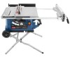
... MITER TABLE outfeed support LOCK knob MITER FENCE SCALE miter scale BLADE GUARD BEVEL LOCKING LEVER RIP FENCE table extension LOCKING lever TABLE TILT HANDLE SWITCH ASSEMBLY STORAGE BRACKET(S) HEIGHT/bevel ADJUSTING HANDWHEEL BEVEL INDICATOR BEVEL SCALE FRONT RAIL leg stand quick stop Fig. 2 9 Blade Diameter 10 in . Cutting Depth at...
... MITER TABLE outfeed support LOCK knob MITER FENCE SCALE miter scale BLADE GUARD BEVEL LOCKING LEVER RIP FENCE table extension LOCKING lever TABLE TILT HANDLE SWITCH ASSEMBLY STORAGE BRACKET(S) HEIGHT/bevel ADJUSTING HANDWHEEL BEVEL INDICATOR BEVEL SCALE FRONT RAIL leg stand quick stop Fig. 2 9 Blade Diameter 10 in . Cutting Depth at...

User Manual
Page 10
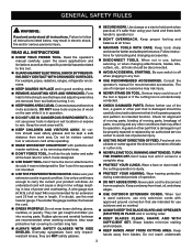
... through sawing, or "up" position, it is provided with optional clamps and accessories. SCALE - This saw has an easy access power switch located below the saw is below the front rail. This handwheel also makes the adjustment for miter and compound miter cuts as well as...kickback. When in place, this table extension gives the operator additional support when cutting wide workpieces. Located on the front of this tool. SWITCH ASSEMBLY - This saw blade teeth. The blade is inaccessible to children and others not qualified to lower and raise the blade for rip cuts...
... through sawing, or "up" position, it is provided with optional clamps and accessories. SCALE - This saw has an easy access power switch located below the saw is below the front rail. This handwheel also makes the adjustment for miter and compound miter cuts as well as...kickback. When in place, this table extension gives the operator additional support when cutting wide workpieces. Located on the front of this tool. SWITCH ASSEMBLY - This saw blade teeth. The blade is inaccessible to children and others not qualified to lower and raise the blade for rip cuts...
User Manual
Page 11
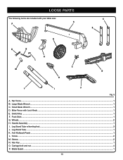
...an angle by an insert called the throat plate. This feature is not in contact with the blade before plugging tool into the switch, lift the switch to prevent unauthorized and possible hazardous use and keep it in a safe place. In the event of the cabinet. Warning: To... use by children and others. It is surrounded by loosening the adjusting clamp, setting the fence to turn the switch OFF ( O ) and remove the key. SWITCH ON SWITCH OFF SWITCH KEY SWITCH IN LOCKED POSITION 11 Fig. 3 With the miter fence removed, the miter table offers additional support for all ...
...an angle by an insert called the throat plate. This feature is not in contact with the blade before plugging tool into the switch, lift the switch to prevent unauthorized and possible hazardous use and keep it in a safe place. In the event of the cabinet. Warning: To... use by children and others. It is surrounded by loosening the adjusting clamp, setting the fence to turn the switch OFF ( O ) and remove the key. SWITCH ON SWITCH OFF SWITCH KEY SWITCH IN LOCKED POSITION 11 Fig. 3 With the miter fence removed, the miter table offers additional support for all ...
User Manual
Page 13
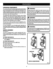
LOOSE PARTS The following items are included with Lock Knob...1 E. Handle Assembly...1 I. Switch Key...1 F. Wheels...2 H. Hex Key...1 O. Small Blade Wrench...1 D. Blade Guard...1 13 Sleeve...2 N. Miter Fence with your table saw: A P c b g o n k l e m d h j i f Fig. 5 A. Anti-Kickback Pawls...1 L. Rip Fence...1 B. Leg Stand Tube...1 K. Large Blade Wrench...1 C. Screw...2 M. Push Stick...1 G. Leg Stand Tube w/leveling foot...3 J. Carriage bolt and nut...4 P.
LOOSE PARTS The following items are included with Lock Knob...1 E. Handle Assembly...1 I. Switch Key...1 F. Wheels...2 H. Hex Key...1 O. Small Blade Wrench...1 D. Blade Guard...1 13 Sleeve...2 N. Miter Fence with your table saw: A P c b g o n k l e m d h j i f Fig. 5 A. Anti-Kickback Pawls...1 L. Rip Fence...1 B. Leg Stand Tube...1 K. Large Blade Wrench...1 C. Screw...2 M. Push Stick...1 G. Leg Stand Tube w/leveling foot...3 J. Carriage bolt and nut...4 P.

User Manual
Page 32
.... Make sure the wood is a high-quality combination blade suitable for the blade to come to heed this tool. SWITCH ON SWITCH OFF SWITCH KEY SWITCH IN LOCKED POSITION 32 Fig. 42 Fig. 43 Always tighten the lock knob securely in personal injury. operation MAKING CUTS The blade...fence in kickback which can cause serious personal injury. Wait for ripping and cross cut operations. NOTE: To prevent unauthorized use, remove the switch key as a cutoff gauge when cross cutting will result in place by twisting the lock knob clockwise. Failure to a complete stop before ...
.... Make sure the wood is a high-quality combination blade suitable for the blade to come to heed this tool. SWITCH ON SWITCH OFF SWITCH KEY SWITCH IN LOCKED POSITION 32 Fig. 42 Fig. 43 Always tighten the lock knob securely in personal injury. operation MAKING CUTS The blade...fence in kickback which can cause serious personal injury. Wait for ripping and cross cut operations. NOTE: To prevent unauthorized use, remove the switch key as a cutoff gauge when cross cutting will result in place by twisting the lock knob clockwise. Failure to a complete stop before ...
User Manual
Page 38
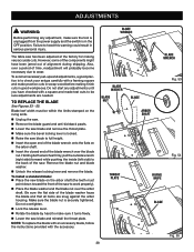
... the blade nut is in serious personal injury. Do not start any adjustment, make sure the tool is unplugged from the power supply and the switch is securely tightened. Holding both wrenches firmly, pull the outside wrench (right side) forward while pushing the inside (left side) to be within the limits...
... the blade nut is in serious personal injury. Do not start any adjustment, make sure the tool is unplugged from the power supply and the switch is securely tightened. Holding both wrenches firmly, pull the outside wrench (right side) forward while pushing the inside (left side) to be within the limits...
User Manual
Page 40
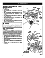
... THE ALIGNMENT OF THE RIP FENCE TO THE BLADE See Figure 58. Unplug the saw back in to make test cuts, make sure the switch is in the off position and the blade guard is in serious injury. Failure to check the other side. If the two dimensions are...
... THE ALIGNMENT OF THE RIP FENCE TO THE BLADE See Figure 58. Unplug the saw back in to make test cuts, make sure the switch is in the off position and the blade guard is in serious injury. Failure to check the other side. If the two dimensions are...

User Manual
Page 41
... destroy plastic which may be damaged by their use any attachments or accessories not recommended by cleaning out sawdust from the power supply and the switch is in contact with a soft damp cloth. Use a resin solvent on the blade teeth. Clean plastic parts only with plastic parts. Most plastics are...
... destroy plastic which may be damaged by their use any attachments or accessories not recommended by cleaning out sawdust from the power supply and the switch is in contact with a soft damp cloth. Use a resin solvent on the blade teeth. Clean plastic parts only with plastic parts. Most plastics are...

User Manual
Page 42
...lever down position. Wood is not plugged in. Clean the gears or screw post. Motor cord or wall cord is warped. Cord or switch is fed too fast. Work is damaged. Reset circuit breaker. Troubleshooting Problem Cutting binds or burns work. Change blade; Cause Solution Blade... is not at your nearest authorized service center. Adjust the miter fence. Have the cord or switch replaced at full down . Replace with saw dust. Locking lever is dull. Wood edges away from rip fence when ripping. Blade makes...
...lever down position. Wood is not plugged in. Clean the gears or screw post. Motor cord or wall cord is warped. Cord or switch is fed too fast. Work is damaged. Reset circuit breaker. Troubleshooting Problem Cutting binds or burns work. Change blade; Cause Solution Blade... is not at your nearest authorized service center. Adjust the miter fence. Have the cord or switch replaced at full down . Replace with saw dust. Locking lever is dull. Wood edges away from rip fence when ripping. Blade makes...

User Manual 4
Page 6
...Key No. 12)........ 1 Screw (M4 x 18 mm, Pan Hd 4 Switch Key 1 Cord Clamp (3/8 in . TABLE SAW - MODEL NUMBER RTS31 The model number will be found on a label attached to the cabinet. Key Nos. 9 and 50-51 1 Strain Relief 1 Switch Assembly w/Key (Inc. Hd 2 Hand Wheel 1 Lock Nut (1/4-20 1 ... x D26 x 2t 1 Rubber Pad 1 Lock Lever 1 Lock Screw 1 Lock Bushing 1 Screw (8-32 x 1 in . PARTS LIST FOR FIGURE B KEY PART NO. Soc. RYOBI 10 in ., Pan Hd 1 Cam 1 Rack 1 Bevel Scale Label 1 Indicator 1 Screw w/Washer (M5 x 8 mm, Rnd. PORTABLE TABLE SAW or when ordering parts. Hd...
...Key No. 12)........ 1 Screw (M4 x 18 mm, Pan Hd 4 Switch Key 1 Cord Clamp (3/8 in . TABLE SAW - MODEL NUMBER RTS31 The model number will be found on a label attached to the cabinet. Key Nos. 9 and 50-51 1 Strain Relief 1 Switch Assembly w/Key (Inc. Hd 2 Hand Wheel 1 Lock Nut (1/4-20 1 ... x D26 x 2t 1 Rubber Pad 1 Lock Lever 1 Lock Screw 1 Lock Bushing 1 Screw (8-32 x 1 in . PARTS LIST FOR FIGURE B KEY PART NO. Soc. RYOBI 10 in ., Pan Hd 1 Cam 1 Rack 1 Bevel Scale Label 1 Indicator 1 Screw w/Washer (M5 x 8 mm, Rnd. PORTABLE TABLE SAW or when ordering parts. Hd...


