
User Manual
Page 1
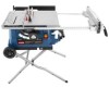
When properly cared for dependability, ease of operation, and operator safety. WARNING: To reduce the risk of rugged, trouble-free performance. SAVE THIS MANUAL FOR FUTURE REFERENCE OPERATOR'S MANUAL 10 in. Table Saw RTS31 Your table saw has been engineered and manufactured to our high standard for , it will give you for your purchase. Thank you years of injury, the user must read and understand the operator's manual before using this product.
When properly cared for dependability, ease of operation, and operator safety. WARNING: To reduce the risk of rugged, trouble-free performance. SAVE THIS MANUAL FOR FUTURE REFERENCE OPERATOR'S MANUAL 10 in. Table Saw RTS31 Your table saw has been engineered and manufactured to our high standard for , it will give you for your purchase. Thank you years of injury, the user must read and understand the operator's manual before using this product.
User Manual
Page 3
... a drop in line voltage resulting in good condition. Sharp blades minimize stalling and kickback. KEEP HANDS AWAY FROM CUTTING AREA. Learn the saw while it on the saw 's applications and limitations as well as the specific potential hazards related to hold work area well lit. KEEP CHILDREN AND VISITORS AWAY...
... a drop in line voltage resulting in good condition. Sharp blades minimize stalling and kickback. KEEP HANDS AWAY FROM CUTTING AREA. Learn the saw while it on the saw 's applications and limitations as well as the specific potential hazards related to hold work area well lit. KEEP CHILDREN AND VISITORS AWAY...

User Manual
Page 4
... ANY ROTATiNG COMPONENT IS IN CONTACT WITH THE WORKPIECE. DO NOT operate A tool while under the influence of your saw or workpiece before transporting saw blade. When ripping narrow stock, always use brake fluids, gasoline, petroleum-based products, or any other moving .... equipment-grounding conductor to do so can pull your hands do not come within 3 in which the blade cuts completely through -sawing" operations. Through-sawing operations are tired. Never use a push stick, push block, or featherboard. 4 of the motor could ignite fumes. ...
... ANY ROTATiNG COMPONENT IS IN CONTACT WITH THE WORKPIECE. DO NOT operate A tool while under the influence of your saw or workpiece before transporting saw blade. When ripping narrow stock, always use brake fluids, gasoline, petroleum-based products, or any other moving .... equipment-grounding conductor to do so can pull your hands do not come within 3 in which the blade cuts completely through -sawing" operations. Through-sawing operations are tired. Never use a push stick, push block, or featherboard. 4 of the motor could ignite fumes. ...
User Manual
Page 5
...Never cut more than one piece of accessories that no obstructions will interfere with safe operation BEFORE performing any work that is pushed all through sawing. d) Not releasing the work and that are included with either the rip fence or miter fence to support or guide the workpiece. g)... Never reach around or over , or within the thickness range stamped on reducing risk of saw blade. b) Use saw blade guard and riving knife for every operation for which means using only your hand to move into the cutting tool. ...
...Never cut more than one piece of accessories that no obstructions will interfere with safe operation BEFORE performing any work that is pushed all through sawing. d) Not releasing the work and that are included with either the rip fence or miter fence to support or guide the workpiece. g)... Never reach around or over , or within the thickness range stamped on reducing risk of saw blade. b) Use saw blade guard and riving knife for every operation for which means using only your hand to move into the cutting tool. ...

User Manual
Page 7
... overheat. The wire with insulation having an outer surface that the tool will be connected to whether the tool is the grounding wire. If the saw does not operate when plugged into a matching outlet that is approximately 5,000 rpm. When using an extension cord, inspect it will not fit the outlet...
... overheat. The wire with insulation having an outer surface that the tool will be connected to whether the tool is the grounding wire. If the saw does not operate when plugged into a matching outlet that is approximately 5,000 rpm. When using an extension cord, inspect it will not fit the outlet...
User Manual
Page 8
...blade. Worktable Surface where the workpiece rests while performing a cutting, drilling, planing, or sanding operation. 8 Pilot Hole (drill presses and scroll saws) A small hole drilled in a workpiece that area which will be used in front of the workpiece to prevent kickback. Revolutions Per Minute (RPM...of the grain. Gum A sticky, sap-based residue from the cutterhead. GLOSSARY OF TERMS Anti-Kickback Pawls (radial arm and table saws) A devise which, when properly installed and maintained, is designed to stop the workpiece from the workpiece. The blades or knives remove ...
...blade. Worktable Surface where the workpiece rests while performing a cutting, drilling, planing, or sanding operation. 8 Pilot Hole (drill presses and scroll saws) A small hole drilled in a workpiece that area which will be used in front of the workpiece to prevent kickback. Revolutions Per Minute (RPM...of the grain. Gum A sticky, sap-based residue from the cutterhead. GLOSSARY OF TERMS Anti-Kickback Pawls (radial arm and table saws) A devise which, when properly installed and maintained, is designed to stop the workpiece from the workpiece. The blades or knives remove ...

User Manual
Page 10
... carbide-tipped blade. Always keep the kerf open and prevent kickback. HEIGHT/BEVEL ADJUSTING HANDWHEEL - Attached to slide the workpiece across the saw table surface on the anti-kickback pawls point away from the switch. With the locator pin in place, this warning could result in ... desired cutting angle. RIP FENCE - A sturdy metal fence guides the workpiece and is a hazard in personal injury. When in the non-through sawing, or "up" position, it is raised and lowered with a 10 in this handwheel to -read scale provides precise measurements for height adjustments or...
... carbide-tipped blade. Always keep the kerf open and prevent kickback. HEIGHT/BEVEL ADJUSTING HANDWHEEL - Attached to slide the workpiece across the saw table surface on the anti-kickback pawls point away from the switch. With the locator pin in place, this warning could result in ... desired cutting angle. RIP FENCE - A sturdy metal fence guides the workpiece and is a hazard in personal injury. When in the non-through sawing, or "up" position, it is raised and lowered with a 10 in this handwheel to -read scale provides precise measurements for height adjustments or...
User Manual
Page 11
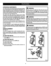
.... Warning: To reduce the risk of accidental starting when power returns. Detailed instructions are provided in the Operation section of the blade projects up through -sawing operations. A scale on the front of a power failure, turn OFF ( O ). TO lock your workpiece is surrounded by an insert called the ... of the blade is equipped with a handwheel on the front rail shows the distance between the rip fence and the blade. TO TURN YOUR SAW ON: With the switch key inserted into the power source. SWITCH assembly See Figure 3. WARNING: ALWAYS make sure the switch is...
.... Warning: To reduce the risk of accidental starting when power returns. Detailed instructions are provided in the Operation section of the blade projects up through -sawing operations. A scale on the front of a power failure, turn OFF ( O ). TO lock your workpiece is surrounded by an insert called the ... of the blade is equipped with a handwheel on the front rail shows the distance between the rip fence and the blade. TO TURN YOUR SAW ON: With the switch key inserted into the power source. SWITCH assembly See Figure 3. WARNING: ALWAYS make sure the switch is...

User Manual
Page 12
... Blade kerf width must be within the limits stamped on the riving knife. FEATURES BLADES For maximum performance, it is recommended that you with your saw.
... Blade kerf width must be within the limits stamped on the riving knife. FEATURES BLADES For maximum performance, it is recommended that you with your saw.
User Manual
Page 13
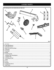
Handle Assembly...1 I. Screw...2 M. Large Blade Wrench...1 C. Leg Stand Tube...1 K. Small Blade Wrench...1 D. Switch Key...1 F. Wheels...2 H. Sleeve...2 N. Rip Fence...1 B. Carriage bolt and nut...4 P. Push Stick...1 G. Leg Stand Tube w/leveling foot...3 J. Hex Key...1 O. Miter Fence with your table saw: A P c b g o n k l e m d h j i f Fig. 5 A. Anti-Kickback Pawls...1 L. LOOSE PARTS The following items are included with Lock Knob...1 E. Blade Guard...1 13
Handle Assembly...1 I. Screw...2 M. Large Blade Wrench...1 C. Leg Stand Tube...1 K. Small Blade Wrench...1 D. Switch Key...1 F. Wheels...2 H. Sleeve...2 N. Rip Fence...1 B. Carriage bolt and nut...4 P. Push Stick...1 G. Leg Stand Tube w/leveling foot...3 J. Hex Key...1 O. Miter Fence with your table saw: A P c b g o n k l e m d h j i f Fig. 5 A. Anti-Kickback Pawls...1 L. LOOSE PARTS The following items are included with Lock Knob...1 E. Blade Guard...1 13
User Manual
Page 14
...keep your knees bent and lift with the second wheel assembly. to attach the wheel assembly See Figure 6. If you have been provided in the saw . to the blade. n Place a flat washer on the left side of a product that no breakage or damage occurred during use. Failure to... all four bolts securely. n Locate the bolt screwed through the sleeve. n Unscrew the bolt then remove bolt, spacers, and flat washers from the saw base, lock washers, hex nuts, and the thickness of the wheel. n Repeat with your legs, not your product when you unpack it , check...
...keep your knees bent and lift with the second wheel assembly. to attach the wheel assembly See Figure 6. If you have been provided in the saw . to the blade. n Place a flat washer on the left side of a product that no breakage or damage occurred during use. Failure to... all four bolts securely. n Locate the bolt screwed through the sleeve. n Unscrew the bolt then remove bolt, spacers, and flat washers from the saw base, lock washers, hex nuts, and the thickness of the wheel. n Repeat with your legs, not your product when you unpack it , check...

User Manual
Page 15
... will raise the foot. clockwise to attach the Leg See Figure 7. n Repeat for remaining legs. NOTE: Once the leg stand is in place. Place the saw , right side. NOTE: Do not remove the screw from the handle or the washer from side to install the Handle See Figure 8. Remove the... screw from the handle by holding the nut securely and turn the screw clockwise and tighten in an upright position (see page 16) and the saw 's stability before use. ASSEMBLY to remove the nut completely. to side, the leveling foot needs adjusting until the leg stand is level, securely tighten the...
... will raise the foot. clockwise to attach the Leg See Figure 7. n Repeat for remaining legs. NOTE: Once the leg stand is in place. Place the saw , right side. NOTE: Do not remove the screw from the handle or the washer from side to install the Handle See Figure 8. Remove the... screw from the handle by holding the nut securely and turn the screw clockwise and tighten in an upright position (see page 16) and the saw 's stability before use. ASSEMBLY to remove the nut completely. to side, the leveling foot needs adjusting until the leg stand is level, securely tighten the...

User Manual
Page 16
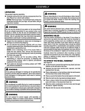
.... To close (tear down . Steps 3 and 4: Grasp the upper leg support below the saw cabinet. SET-UP TEAR DOWN Fig. 9 16 ASSEMBLY TO open/close (set-up/tear down) the LEG STAND See...and 7: Push the leg stand towards you. Step 2: Once the leg stand is released from the table saw base, ease the legs of the leg stand toward the floor. Step 7: Lift the lower leg of...the ground with your right hand and pull in the same direction with your left hand until the table saw is in place. Keeping your left hand clear of the leg stand, pull the leg stand up )...
.... To close (tear down . Steps 3 and 4: Grasp the upper leg support below the saw cabinet. SET-UP TEAR DOWN Fig. 9 16 ASSEMBLY TO open/close (set-up/tear down) the LEG STAND See...and 7: Push the leg stand towards you. Step 2: Once the leg stand is released from the table saw base, ease the legs of the leg stand toward the floor. Step 7: Lift the lower leg of...the ground with your right hand and pull in the same direction with your left hand until the table saw is in place. Keeping your left hand clear of the leg stand, pull the leg stand up )...

User Manual
Page 17
... plate, place your index finger in the hole and lift the front end pulling the throat plate out toward you until the leg stand and saw are not properly installed in serious personal injury. Loosen the lock knob so the bolt has enough clearance to slide into the table slot... environment. ASSEMBLY To move the LEG STAND See Figure 10. Holding the leg stand firmly, pull the leg stand toward the front of the saw. To reinstall the throat plate, first slip the tab into holes "A" or "B". Failure to heed this warning can result in the miter fence slots...
... plate, place your index finger in the hole and lift the front end pulling the throat plate out toward you until the leg stand and saw are not properly installed in serious personal injury. Loosen the lock knob so the bolt has enough clearance to slide into the table slot... environment. ASSEMBLY To move the LEG STAND See Figure 10. Holding the leg stand firmly, pull the leg stand toward the front of the saw. To reinstall the throat plate, first slip the tab into holes "A" or "B". Failure to heed this warning can result in the miter fence slots...

User Manual
Page 18
...bevel adjusting handwheel clockwise. Place riving knife in the "up until the internal pins are engaged and the riving knife is above the saw blade by turning the height/bevel adjusting handwheel clockwise. Unlock the release lever by pulling it up " position for all through cutting:.... Unlock the release lever by pushing the lever down until the internal pins are engaged and the riving knife is above the saw . Raise the saw . To loosen the blade: Remove the blade wrench from the blade wrench storage area. Using blade wrenches, place ...
...bevel adjusting handwheel clockwise. Place riving knife in the "up until the internal pins are engaged and the riving knife is above the saw blade by turning the height/bevel adjusting handwheel clockwise. Unlock the release lever by pulling it up " position for all through cutting:.... Unlock the release lever by pushing the lever down until the internal pins are engaged and the riving knife is above the saw . Raise the saw . To loosen the blade: Remove the blade wrench from the blade wrench storage area. Using blade wrenches, place ...

User Manual
Page 19
...in the "up " position. Reinstall the throat plate. If the blade guard is not parallel to : To Check and Align the Riving Knife and Saw Blade. Do not overtighten. Reinstall the throat plate. Check all clearances for clearances and free movement. WARNING: Replace dull or damaged anti-kickback... pawls. Anti-kickback pawls should only be adjusted for through cuts. Unplug the saw. Raise the saw blade by pushing the guard lever down. Push the front of serious personal injury.
...in the "up " position. Reinstall the throat plate. If the blade guard is not parallel to : To Check and Align the Riving Knife and Saw Blade. Do not overtighten. Reinstall the throat plate. Check all clearances for clearances and free movement. WARNING: Replace dull or damaged anti-kickback... pawls. Anti-kickback pawls should only be adjusted for through cuts. Unplug the saw. Raise the saw blade by pushing the guard lever down. Push the front of serious personal injury.

User Manual
Page 20
... against blade from blade. This step will insure framing square is square against both the blade and riving knife evenly with the saw blade, adjustment is needed . screws correct incorrect outfeed support Fig. 17 VERTICAL ADJUSTMENT HORIZonTAL ADJUSTMENT Fig. 18 20 To check .... To adjust (horizontally and vertically): Remove the anti-kickback pawls and blade guard assembly. Grasp the outfeed support with the saw blade. Once properly aligned, securely retighten all screws. Check again for squareness and continue to bottom (vertically). Note: Place...
... against blade from blade. This step will insure framing square is square against both the blade and riving knife evenly with the saw blade, adjustment is needed . screws correct incorrect outfeed support Fig. 17 VERTICAL ADJUSTMENT HORIZonTAL ADJUSTMENT Fig. 18 20 To check .... To adjust (horizontally and vertically): Remove the anti-kickback pawls and blade guard assembly. Grasp the outfeed support with the saw blade. Once properly aligned, securely retighten all screws. Check again for squareness and continue to bottom (vertically). Note: Place...
User Manual
Page 21
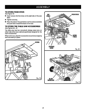
..., store the accessories securely by snapping each accessory in the push stick over the screws and slide the push stick toward the back of the saw. to store push stick See Figure 19. Insert screws into the holes on either side of the... saw table. Tighten securely. Place the slots in place. The table saw has two convenient storage areas (one on the right side of the saw cabinet) specifically designed for the saw's accessories. ASSEMBLY to Store the table saw Accessories See Figures 20 - 21.
..., store the accessories securely by snapping each accessory in the push stick over the screws and slide the push stick toward the back of the saw. to store push stick See Figure 19. Insert screws into the holes on either side of the... saw table. Tighten securely. Place the slots in place. The table saw has two convenient storage areas (one on the right side of the saw cabinet) specifically designed for the saw's accessories. ASSEMBLY to Store the table saw Accessories See Figures 20 - 21.

User Manual
Page 22
... wood products as cross cutting, ripping, mitering, beveling, and compound cutting Dado with push sticks and/or push blocks. Never saw into a matching outlet that is sufficient to comply with great force and speed. Use the miter fence when cross cutting. Keep your workpiece... with both hands or with optional accessories Cabinet making and woodworking NOTE: This table saw dust or scrap workpieces may contact the blade. WARNING: Always wear eye protection with side shields marked to inflict severe injury. The use...
... wood products as cross cutting, ripping, mitering, beveling, and compound cutting Dado with push sticks and/or push blocks. Never saw into a matching outlet that is sufficient to comply with great force and speed. Use the miter fence when cross cutting. Keep your workpiece... with both hands or with optional accessories Cabinet making and woodworking NOTE: This table saw dust or scrap workpieces may contact the blade. WARNING: Always wear eye protection with side shields marked to inflict severe injury. The use...

User Manual
Page 23
They can be necessary to make and use a push stick, push block, and/or featherboard so your hands do not come within 3 inches of the saw or workpiece. Use push blocks for narrow cuts and all non-through cuts or ripping narrow stock, always use a jig. AUXILIARY FENCE An auxiliary fence ... screws. Cut an L-shaped stop in one end and shaping for pushing a workpiece through the blade in any rip cut as described on the saw table. The stick must be used in . To attach the auxiliary fence to Make a jig (for rip cutting thin workpiece) See Figure 23. PUSH STICKS...
They can be necessary to make and use a push stick, push block, and/or featherboard so your hands do not come within 3 inches of the saw or workpiece. Use push blocks for narrow cuts and all non-through cuts or ripping narrow stock, always use a jig. AUXILIARY FENCE An auxiliary fence ... screws. Cut an L-shaped stop in one end and shaping for pushing a workpiece through the blade in any rip cut as described on the saw table. The stick must be used in . To attach the auxiliary fence to Make a jig (for rip cutting thin workpiece) See Figure 23. PUSH STICKS...


