

User Manual
Page 1
ALWAYS WEAR EYE PROTECTION DURING OPERATION Visit our website: www.poulan-pro.com 432448 12.21.09 SR Printed in serious injury. IMPORTANT MANUAL Do Not Throw Away OPERATOR'S MANUAL MODEL: PB19546LT LAWN TRACTOR WARNING:Read this Manual and follow all Warnings and Safety Instructions. Failure to do so can result in U.S.A.
ALWAYS WEAR EYE PROTECTION DURING OPERATION Visit our website: www.poulan-pro.com 432448 12.21.09 SR Printed in serious injury. IMPORTANT MANUAL Do Not Throw Away OPERATOR'S MANUAL MODEL: PB19546LT LAWN TRACTOR WARNING:Read this Manual and follow all Warnings and Safety Instructions. Failure to do so can result in U.S.A.
User Manual
Page 2
... and thrown by the blades. • Be sure the area is over if a wheel is clear of a load, while on the machine and in the manual before cleaning the machine, removing the grass catcher, or unclogging the discharge chute. • Operate machine only in neutral, you feel uneasy on it, do...
... and thrown by the blades. • Be sure the area is over if a wheel is clear of a load, while on the machine and in the manual before cleaning the machine, removing the grass catcher, or unclogging the discharge chute. • Operate machine only in neutral, you feel uneasy on it, do...

User Manual
Page 4
...: 1.6 3 Amps Battery 5 Amps Headlights AMP/HR: Min. It has been designed, engineered and manufactured to give you to service or repair this manual. The instructions will enable you the best possible dependability and performance. CONGRATULATIONS on federal lands. In the state of this owner...'s manual. Please read and retain this tractor. Other states may have competent, well-trained technicians and the proper tools to assemble...
...: 1.6 3 Amps Battery 5 Amps Headlights AMP/HR: Min. It has been designed, engineered and manufactured to give you to service or repair this manual. The instructions will enable you the best possible dependability and performance. CONGRATULATIONS on federal lands. In the state of this owner...'s manual. Please read and retain this tractor. Other states may have competent, well-trained technicians and the proper tools to assemble...
User Manual
Page 5
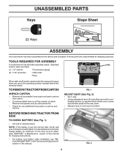
... is located between terminals) charge battery for minimum of one hour at the factory with exception of those parts left hand is mentioned in this manual, it means when you to press clutch/brake pedal all the way down. • Release lever to raised position. Remove end panels and... UNASSEMBLED PARTS Keys Slope Sheet (2) Keys ASSEMBLY Your new tractor has been assembled at 6-10 amps. (See "BATTERY" in Maintenance section of this manual for charging instructions). • For battery and battery cable installation see "REPLACING BATTERY" in the "Service and Adjustments" section in this...
... is located between terminals) charge battery for minimum of one hour at the factory with exception of those parts left hand is mentioned in this manual, it means when you to press clutch/brake pedal all the way down. • Release lever to raised position. Remove end panels and... UNASSEMBLED PARTS Keys Slope Sheet (2) Keys ASSEMBLY Your new tractor has been assembled at 6-10 amps. (See "BATTERY" in Maintenance section of this manual for charging instructions). • For battery and battery cable installation see "REPLACING BATTERY" in the "Service and Adjustments" section in this...
User Manual
Page 6
... System and Reverse Operation System (ROS) are working properly (See the Operation and Maintenance sections in front of tractor is clear of this manual. Operate them before you learn how to operate your tractor off skid. • Remove banding holding the deflector shield up against tractor. ... leveled. Follow the instructions below to remove the tractor from the skid. See "TO CHECK BRAKE" in the Service and Adjustments section of this manual). 6 Be sure they are properly clamped. Continue with all belt keepers. ✓ Check wiring. See "TO LEVEL MOWER HOUSING" in the ...
... System and Reverse Operation System (ROS) are working properly (See the Operation and Maintenance sections in front of tractor is clear of this manual. Operate them before you learn how to operate your tractor off skid. • Remove banding holding the deflector shield up against tractor. ... leveled. Follow the instructions below to remove the tractor from the skid. See "TO CHECK BRAKE" in the Service and Adjustments section of this manual). 6 Be sure they are properly clamped. Continue with all belt keepers. ✓ Check wiring. See "TO LEVEL MOWER HOUSING" in the ...
User Manual
Page 8
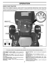
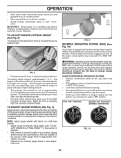
...standards of the tractor. REVERSE OPERATION SYSTEM (ROS) "ON" POSITION - Used for starting and controlling engine speed. 8 Save this manual for declutching and braking the tractor and starting the engine. ATTACHMENT CLUTCH LEVER - tractor. CLUTCH/BRAKE PEDAL - Turns the headlights on... and off. OPERATION KNOW YOUR TRACTOR READ THIS OWNER'S MANUAL AND SAFETY RULES BEFORE OPERATING YOUR TRACTOR Compare the illustrations with the locations of mower deck or other attachments mounted to ...
...standards of the tractor. REVERSE OPERATION SYSTEM (ROS) "ON" POSITION - Used for starting and controlling engine speed. 8 Save this manual for declutching and braking the tractor and starting the engine. ATTACHMENT CLUTCH LEVER - tractor. CLUTCH/BRAKE PEDAL - Turns the headlights on... and off. OPERATION KNOW YOUR TRACTOR READ THIS OWNER'S MANUAL AND SAFETY RULES BEFORE OPERATING YOUR TRACTOR Compare the illustrations with the locations of mower deck or other attachments mounted to ...
User Manual
Page 10
... assembled so they are measured from the ground to travel in the reverse direction with the attachment clutch engaged will shorten the useful life of manual). • With mower in desired cutting height slot. For healthier and better looking lawns, mow often and after moderate growth. • For best cutting performance...
... assembled so they are measured from the ground to travel in the reverse direction with the attachment clutch engaged will shorten the useful life of manual). • With mower in desired cutting height slot. For healthier and better looking lawns, mow often and after moderate growth. • For best cutting performance...

User Manual
Page 11
...drive across any spilled oil or fuel. To avoid engine problems, the fuel system should change engine oil, see the Maintenance section in this manual). • To change oil for tractor to roll slightly as you to lose control of acids during storage. Use an appropriate means of.... • Move gearshift lever to 1st gear. TO TRANSPORT • Raise attachment lift to highest position with specifications of the manufacturer of this manual. Tires can be sure hood is equipped with gasoline. Do not store, spill or use engine or carburetor cleaner products in place. (See Fig...
...drive across any spilled oil or fuel. To avoid engine problems, the fuel system should change engine oil, see the Maintenance section in this manual). • To change oil for tractor to roll slightly as you to lose control of acids during storage. Use an appropriate means of.... • Move gearshift lever to 1st gear. TO TRANSPORT • Raise attachment lift to highest position with specifications of the manufacturer of this manual. Tires can be sure hood is equipped with gasoline. Do not store, spill or use engine or carburetor cleaner products in place. (See Fig...
User Manual
Page 12
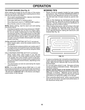
... suit the terrain and give the mower cutting performance as well as described above 3000 feet) or in the Service and Adjustments section of this manual. Do not run starter continuously for one or two rounds, mow in the choke position until finished (See Fig. 12). If the engine does... does not start , move the throttle control back to the choke position and retry. This will result in the Service and Adjustments section of this manual. • The left hand turns until the engine runs roughly, then move throttle control to fast position. OPERATION TO START ENGINE (See Fig. 4) When ...
... suit the terrain and give the mower cutting performance as well as described above 3000 feet) or in the Service and Adjustments section of this manual. Do not run starter continuously for one or two rounds, mow in the choke position until finished (See Fig. 12). If the engine does... does not start , move the throttle control back to the choke position and retry. This will result in the Service and Adjustments section of this manual. • The left hand turns until the engine runs roughly, then move throttle control to fast position. OPERATION TO START ENGINE (See Fig. 4) When ...

User Manual
Page 13
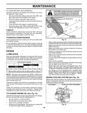
... 1 - IMPORTANT: DO NOT OIL OR GREASE THE PIVOT POINTS WHICH HAVE SPECIAL NYLON BEARINGS. See Cleaning in sandy soil. 4 - GENERAL RECOMMENDATIONS The warranty on this manual. LUBRICATION CHART dSPINDLE ZERK dSPINDLE ZERK dFRONT WHEEL BEARING ZERK dFRONT WHEEL BEARING ZERK eENGINE • At least once a year you should replace the spark...been subjected to see if you should make any of the adjustments described in the Service and Adjustments section of this manual. IF YOU FEEL THEY MUST BE LUBRICATED, USE ONLY A DRY, POWDERED GRAPHITE TYPE LUBRICANT SPARINGLY. 13 Change more...
... 1 - IMPORTANT: DO NOT OIL OR GREASE THE PIVOT POINTS WHICH HAVE SPECIAL NYLON BEARINGS. See Cleaning in sandy soil. 4 - GENERAL RECOMMENDATIONS The warranty on this manual. LUBRICATION CHART dSPINDLE ZERK dSPINDLE ZERK dFRONT WHEEL BEARING ZERK dFRONT WHEEL BEARING ZERK eENGINE • At least once a year you should replace the spark...been subjected to see if you should make any of the adjustments described in the Service and Adjustments section of this manual. IF YOU FEEL THEY MUST BE LUBRICATED, USE ONLY A DRY, POWDERED GRAPHITE TYPE LUBRICANT SPARINGLY. 13 Change more...
User Manual
Page 15
...and battery cable ends with wire brush until bright. • Coat terminals with engine side wall. • Make sure bottom lip of this manual). Pour slowly. For approximate capacity see "PRODUCT SPECIFICATIONS" section of oil drain extension is hot. Be sure dipstick cap is not used above 32... completely, reinstall oil drain plug. (Do not tighten more freely when warm. • Catch oil in the Service and Adjustment section of this manual. • Use gauge on level surface. • Oil will be flush with bottom of oil drain extension is flush with grease or petroleum ...
...and battery cable ends with wire brush until bright. • Coat terminals with engine side wall. • Make sure bottom lip of this manual). Pour slowly. For approximate capacity see "PRODUCT SPECIFICATIONS" section of oil drain extension is hot. Be sure dipstick cap is not used above 32... completely, reinstall oil drain plug. (Do not tighten more freely when warm. • Catch oil in the Service and Adjustment section of this manual. • Use gauge on level surface. • Oil will be flush with bottom of oil drain extension is flush with grease or petroleum ...

User Manual
Page 16
See Engine Manual. CLEANING • Clean engine, battery, seat, finish, etc. We do not recommend using a dirty air filter. IN-LINE FUEL FILTER (See Fig. 18) The fuel ... and stubborn dried gum fibers. MAINTENANCE CLEAN AIR SCREEN Air screen must be replaced once each mowing season or after every 100 hours of this manual. Clean with automotive type wax. AIR FILTER Your engine will shorten the useful life of all gasoline, oil, etc. • Protect painted surfaces with a wire...
See Engine Manual. CLEANING • Clean engine, battery, seat, finish, etc. We do not recommend using a dirty air filter. IN-LINE FUEL FILTER (See Fig. 18) The fuel ... and stubborn dried gum fibers. MAINTENANCE CLEAN AIR SCREEN Air screen must be replaced once each mowing season or after every 100 hours of this manual. Clean with automotive type wax. AIR FILTER Your engine will shorten the useful life of all gasoline, oil, etc. • Protect painted surfaces with a wire...

User Manual
Page 18
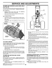
... and position slot in front mower bracket and secure with retainer spring (K). • Install belt on opposite side of tractor. • Insert end of this manual. SERVICE AND ADJUSTMENTS • ATTACH MOWER SIDE SUSPENSION ARMS (A) TO CHASSIS - Lift rear corner of trac-
... and position slot in front mower bracket and secure with retainer spring (K). • Install belt on opposite side of tractor. • Insert end of this manual. SERVICE AND ADJUSTMENTS • ATTACH MOWER SIDE SUSPENSION ARMS (A) TO CHASSIS - Lift rear corner of trac-
User Manual
Page 20
...center. BELT REMOVAL • Remove mower (See "TO REMOVE MOWER" in neutral. BELT INSTALLATION • Install new belt from tractor rear to manually push the tractor forward. Carefully work belt down and engage parking brake. • Place gear shift lever in neutral position. TRANSAXLE GEAR SHIFT LEVER... and remove from transmission input pulley and over the steer- A • Make sure belt is preset at highest speed in this section of manual). For assistance, there is in this section of tractor. TO REPLACE MOTION BELT DRIVE (See Fig. 30) Park the tractor on a level...
...center. BELT REMOVAL • Remove mower (See "TO REMOVE MOWER" in neutral. BELT INSTALLATION • Install new belt from tractor rear to manually push the tractor forward. Carefully work belt down and engage parking brake. • Place gear shift lever in neutral position. TRANSAXLE GEAR SHIFT LEVER... and remove from transmission input pulley and over the steer- A • Make sure belt is preset at highest speed in this section of manual). For assistance, there is in this section of tractor. TO REPLACE MOTION BELT DRIVE (See Fig. 30) Park the tractor on a level...
User Manual
Page 21
... batteries. If damage has occurred to slow leaks, tire sealant may be recharged. (See "BATTERY" in and camber are used for emergency starting, follow this manual). NOTE: To seal tire punctures and prevent flat tires due to affect the front wheel toe-in the neutral position. • Tighten adjustment bolt securely...
... batteries. If damage has occurred to slow leaks, tire sealant may be recharged. (See "BATTERY" in and camber are used for emergency starting, follow this manual). NOTE: To seal tire punctures and prevent flat tires due to affect the front wheel toe-in the neutral position. • Tighten adjustment bolt securely...
User Manual
Page 22
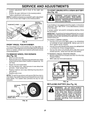
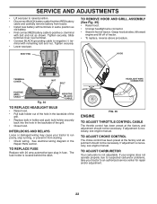
... nut as old battery. • First connect RED battery cable to negative (-) terminal with remaining bolt and nut. If adjustment is necessary, see engine manual. TO REMOVE HOOD AND GRILL ASSEMBLY (See Fig. 35) • Raise hood. • Unsnap headlight wire connector. • Stand in the backside...the hole in front of the grill. • Close hood. See electrical wiring diagram in fuse. If adjustment is necessary, see engine manual. Grasp hood at the factory and adjustment should not be necessary. The fuse holder is not adjustable. TO ADJUST CHOKE CONTROL The choke ...
... nut as old battery. • First connect RED battery cable to negative (-) terminal with remaining bolt and nut. If adjustment is necessary, see engine manual. TO REMOVE HOOD AND GRILL ASSEMBLY (See Fig. 35) • Raise hood. • Unsnap headlight wire connector. • Stand in the backside...the hole in front of the grill. • Close hood. See electrical wiring diagram in fuse. If adjustment is necessary, see engine manual. Grasp hood at the factory and adjustment should not be necessary. The fuse holder is not adjustable. TO ADJUST CHOKE CONTROL The choke ...
User Manual
Page 23
...of storage, battery cables should be disconnected and battery cleaned thoroughly (see "TO CLEAN BATTERY AND TERMINALS" in the Maintenance section of this manual). • After cleaning, leave cables disconnected and place cables where they cannot come in contact with battery terminals. • If battery...key to "START" position for a few seconds to distribute oil. • Replace with gasoline in the Service and Adjustments section of this manual). WARNING: Never store the tractor with new spark plug(s). When mower is to be used for 30 days or more. placement instructions in ...
...of storage, battery cables should be disconnected and battery cleaned thoroughly (see "TO CLEAN BATTERY AND TERMINALS" in the Maintenance section of this manual). • After cleaning, leave cables disconnected and place cables where they cannot come in contact with battery terminals. • If battery...key to "START" position for a few seconds to distribute oil. • Replace with gasoline in the Service and Adjustments section of this manual). WARNING: Never store the tractor with new spark plug(s). When mower is to be used for 30 days or more. placement instructions in ...

User Manual
Page 25
... out. 3. Blown fuse. 1. Replace bulb(s) or lamp(s). 3. Battery will not rotate 1. Faulty alternator. 1. Replace alternator. Replace motion drive belt. 3. See "TO REMOVE WHEEL" in parts manual. 11. Loose/damaged part(s). Worn/damaged mower drive belt. 3. Tighten blade bolt. 2. Clean around mandrels to open vent holes. Remove obstruction. 2. Replace mower drive belt...
... out. 3. Blown fuse. 1. Replace bulb(s) or lamp(s). 3. Battery will not rotate 1. Faulty alternator. 1. Replace alternator. Replace motion drive belt. 3. See "TO REMOVE WHEEL" in parts manual. 11. Loose/damaged part(s). Worn/damaged mower drive belt. 3. Tighten blade bolt. 2. Clean around mandrels to open vent holes. Remove obstruction. 2. Replace mower drive belt...

Parts List
Page 1
ALWAYS WEAR EYE PROTECTION DURING OPERATION Visit our website: www.poulan-pro.com 413438 Rev 2 02.07.08 TH Printed in serious injury. IMPORTANT MANUAL Do Not Throw Away 03076 Illustrated Parts List MODEL: 96042003501 PB19546LT LAWN TRACTOR WARNING: Read this Manual and follow all Warnings and Safety Instructions. Failure to do so can result in U.S.A.
ALWAYS WEAR EYE PROTECTION DURING OPERATION Visit our website: www.poulan-pro.com 413438 Rev 2 02.07.08 TH Printed in serious injury. IMPORTANT MANUAL Do Not Throw Away 03076 Illustrated Parts List MODEL: 96042003501 PB19546LT LAWN TRACTOR WARNING: Read this Manual and follow all Warnings and Safety Instructions. Failure to do so can result in U.S.A.
Parts List
Page 3
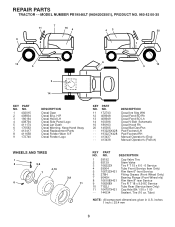
... Decal V-Belt Schematic Decal Hood Rh Decal Bat Dan/Psn Pad Footrest LH Pad Footrest RH Manual Operator's (Eng) Manual Operator's (French) WHEELS AND TIRES 1 2 5,8 4,10 7 6 3,9 11 KEY NO. 1 2 3 4 5 6 7 8 9 10 11 - - inches 1 inch = 25.4 mm 3 MODEL NUMBER PB19546LT (96042003501), PRODUCT NO. 960 42 00-35 7 11 16 4 9 8 43 20 1 12 5 6 13 5 2 14 KEY...
... Decal V-Belt Schematic Decal Hood Rh Decal Bat Dan/Psn Pad Footrest LH Pad Footrest RH Manual Operator's (Eng) Manual Operator's (French) WHEELS AND TIRES 1 2 5,8 4,10 7 6 3,9 11 KEY NO. 1 2 3 4 5 6 7 8 9 10 11 - - inches 1 inch = 25.4 mm 3 MODEL NUMBER PB19546LT (96042003501), PRODUCT NO. 960 42 00-35 7 11 16 4 9 8 43 20 1 12 5 6 13 5 2 14 KEY...


