Service Manual
Page 5
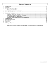
... Defect Specification 18 5. Go to polaroid.com to the User 19 6. Disassembly Procedure ...20 Stand and Control Box Removal 21 Rear Cabinet Cover, LCD Panel and Front Bezel 23 IR Board Removal and Replacement 28 Front/Side Control Buttons Removal and Replacement 29 7. Table of ...Troubleshooting / Flow Charts...14 Factory Mode Procedure...14 4. Exploded View Diagram ...31 9. Specifications ...6 2. Before Returning This Product to obtain User Manual. 5 www.polaroid.com Block Diagram ...32 10. PCB Layout Diagrams ...42 Model Specifications are located in User Manual.
... Defect Specification 18 5. Go to polaroid.com to the User 19 6. Disassembly Procedure ...20 Stand and Control Box Removal 21 Rear Cabinet Cover, LCD Panel and Front Bezel 23 IR Board Removal and Replacement 28 Front/Side Control Buttons Removal and Replacement 29 7. Table of ...Troubleshooting / Flow Charts...14 Factory Mode Procedure...14 4. Exploded View Diagram ...31 9. Specifications ...6 2. Before Returning This Product to obtain User Manual. 5 www.polaroid.com Block Diagram ...32 10. PCB Layout Diagrams ...42 Model Specifications are located in User Manual.
Service Manual
Page 20
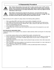
...and packing foam. • Remove replacement components from the wall outlet. 6. Disassembly Procedure Note: Before disassembly of the bags provide electrostatic protection. • Always hold components you begin disassembly. When servicing an LCD or plasma TV, always observe the following safety guidelines: • Wear a grounding (ESD)... attach it to a bare metal part of antistatic bags because only the inside an LCD or plasma TV are ready to discharge before touching any components. 20 www.polaroid.com Allow time for removing screws. • To help keep track of screws, ...
...and packing foam. • Remove replacement components from the wall outlet. 6. Disassembly Procedure Note: Before disassembly of the bags provide electrostatic protection. • Always hold components you begin disassembly. When servicing an LCD or plasma TV, always observe the following safety guidelines: • Wear a grounding (ESD)... attach it to a bare metal part of antistatic bags because only the inside an LCD or plasma TV are ready to discharge before touching any components. 20 www.polaroid.com Allow time for removing screws. • To help keep track of screws, ...
Service Manual
Page 21
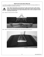
...OFF, and the power cord is removed from the TV Stand. A 21 www.polaroid.com A (2) Remove 3 screws (A) from the Control Box Cover, and remove the Cover from being scratched. Use protective cloth between work bench and TV front. Note: Before disassembly of any objects into the vent holes in the... TV case. (1) Remove 6 screws (A) from the wall outlet. Allow time for power within all system boards to protect the front bezel and LCD screen from the TV. Stand and Control Box Removal...
...OFF, and the power cord is removed from the TV Stand. A 21 www.polaroid.com A (2) Remove 3 screws (A) from the Control Box Cover, and remove the Cover from being scratched. Use protective cloth between work bench and TV front. Note: Before disassembly of any objects into the vent holes in the... TV case. (1) Remove 6 screws (A) from the wall outlet. Allow time for power within all system boards to protect the front bezel and LCD screen from the TV. Stand and Control Box Removal...

Service Manual
Page 23
... removing so the bezel is removed from the wall outlet. Ensure LCD panel is completely detached from the bezel before you begin disassembly. A 23 www.polaroid.com Allow time for power within all models. Never insert any part the TV, make sure the power is OFF, and the power cord is... not damaged. (1) Remove 6 screws (A) from the rear cabinet cover. Rear Cabinet Cover, LCD Panel and Front Bezel Note...
... removing so the bezel is removed from the wall outlet. Ensure LCD panel is completely detached from the bezel before you begin disassembly. A 23 www.polaroid.com Allow time for power within all models. Never insert any part the TV, make sure the power is OFF, and the power cord is... not damaged. (1) Remove 6 screws (A) from the rear cabinet cover. Rear Cabinet Cover, LCD Panel and Front Bezel Note...
Service Manual
Page 28
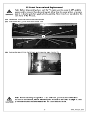
... discharge before you must follow the steps outlined in the TV case. (1) Disassemble control box cover and rear cabinet cover. (2) Remove 8 screws (A) from the TV. This procedure ensures that the chassis will not cause electric shock. 28 www.polaroid.com A Note: Before returning this product to the end... user, you begin disassembly. Never insert any part the TV, make sure the power is OFF, and the...
... discharge before you must follow the steps outlined in the TV case. (1) Disassemble control box cover and rear cabinet cover. (2) Remove 8 screws (A) from the TV. This procedure ensures that the chassis will not cause electric shock. 28 www.polaroid.com A Note: Before returning this product to the end... user, you begin disassembly. Never insert any part the TV, make sure the power is OFF, and the...
Service Manual
Page 29
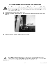
...Never insert any part the TV, make sure the power is OFF, and the power cord is attached with glue. This procedure ensures that the chassis will not cause electric shock. 29 www.polaroid.com Front/Side Control Buttons Removal and Replacement Note: Before disassembly of any objects into the...button board (A). A (3) Replace control button board and use glue to fasten to discharge before you must follow the steps outlined in the TV case. (1) Disassemble control box cover and rear cabinet cover. (2) The control button board is removed from the wall outlet. Use alcohol to the end user...
...Never insert any part the TV, make sure the power is OFF, and the power cord is attached with glue. This procedure ensures that the chassis will not cause electric shock. 29 www.polaroid.com Front/Side Control Buttons Removal and Replacement Note: Before disassembly of any objects into the...button board (A). A (3) Replace control button board and use glue to fasten to discharge before you must follow the steps outlined in the TV case. (1) Disassemble control box cover and rear cabinet cover. (2) The control button board is removed from the wall outlet. Use alcohol to the end user...

User Guide
Page 4
... qualified service personnel. WARNING This symbol is an important feature. Use of controls, adjustments or performance of electric shock. This equipment must be disassembled by the manufacturer. The grounding pin on the rear of important operating and maintenance instructions in hazardous radiation exposure. Before operating this equipment, please read...
... qualified service personnel. WARNING This symbol is an important feature. Use of controls, adjustments or performance of electric shock. This equipment must be disassembled by the manufacturer. The grounding pin on the rear of important operating and maintenance instructions in hazardous radiation exposure. Before operating this equipment, please read...