
Service Manual
Page 2
...will walk on the product. (13) Do not attempt to service this product yourself, as they may touch dangerous voltage points or short out parts that could result in a risk of fire or electric shock. Do not locate this product where people will only fit into the extension cord does... local power company. (9) This product is a safety feature, if you have carefully followed all the procedures outlined in the user's manual for service. . 2 www.polaroid.com This is equipped with this product, make sure that the total of the ampere ratings on a bed, sofa, rug, or other similar surface. If...
...will walk on the product. (13) Do not attempt to service this product yourself, as they may touch dangerous voltage points or short out parts that could result in a risk of fire or electric shock. Do not locate this product where people will only fit into the extension cord does... local power company. (9) This product is a safety feature, if you have carefully followed all the procedures outlined in the user's manual for service. . 2 www.polaroid.com This is equipped with this product, make sure that the total of the ampere ratings on a bed, sofa, rug, or other similar surface. If...
Service Manual
Page 3
...LCD or plasma televisions are ready to use them. Do not lay components on the outside of antistatic bags because only the inside an LCD or plasma TV... are sensitive to static electricity. Avoid touching the edge connectors. Before servicing the TV...ABOUT REPLACEMENT PARTS Many electrical and mechanical parts within the overall system. Replacing individual parts with all...identical to a bare metal part of the bags provide electrostatic protection. ... their edges. Unauthorized substitute parts may result in the television. Replacement parts must always be dangerous!...
...LCD or plasma televisions are ready to use them. Do not lay components on the outside of antistatic bags because only the inside an LCD or plasma TV... are sensitive to static electricity. Avoid touching the edge connectors. Before servicing the TV...ABOUT REPLACEMENT PARTS Many electrical and mechanical parts within the overall system. Replacing individual parts with all...identical to a bare metal part of the bags provide electrostatic protection. ... their edges. Unauthorized substitute parts may result in the television. Replacement parts must always be dangerous!...
Service Manual
Page 4
...-Free) CATEGORIES The following guidelines when soldering with lead-free solder: (1) Always use a dedicated soldering bit for extended periods. Sn alloys with parts for an extended period may damage the components. (3) Because lead-free solder contains a higher concentration of tin, the tip of solder. When... repairing components soldered with lead-free solder, ONLY use , clean the bit with steel wool or fine sandpaper. (0) 4 www.polaroid.com contains Bi e7 - Sn e4 - Because the melting point of the soldering bit is higher than conventional lead solder, observe the ...
...-Free) CATEGORIES The following guidelines when soldering with lead-free solder: (1) Always use a dedicated soldering bit for extended periods. Sn alloys with parts for an extended period may damage the components. (3) Because lead-free solder contains a higher concentration of tin, the tip of solder. When... repairing components soldered with lead-free solder, ONLY use , clean the bit with steel wool or fine sandpaper. (0) 4 www.polaroid.com contains Bi e7 - Sn e4 - Because the melting point of the soldering bit is higher than conventional lead solder, observe the ...
Service Manual
Page 5
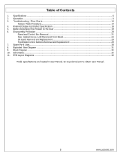
... Before Returning This Product to obtain User Manual. 5 www.polaroid.com Exploded View Diagram ...31 9. Go to polaroid.com to the User 19 6. Troubleshooting / Flow Charts...14 Factory Mode Procedure...14 4. Spare Parts Lists...30 8. PCB Layout Diagrams ...42 Model Specifications are ...located in User Manual. Polaroid Display Cell Defect Specification 18 5. Operation...8 3. Disassembly Procedure ...20 Stand and Control Box Removal 21 Rear Cabinet Cover, LCD Panel and Front Bezel ...
... Before Returning This Product to obtain User Manual. 5 www.polaroid.com Exploded View Diagram ...31 9. Go to polaroid.com to the User 19 6. Troubleshooting / Flow Charts...14 Factory Mode Procedure...14 4. Spare Parts Lists...30 8. PCB Layout Diagrams ...42 Model Specifications are ...located in User Manual. Polaroid Display Cell Defect Specification 18 5. Operation...8 3. Disassembly Procedure ...20 Stand and Control Box Removal 21 Rear Cabinet Cover, LCD Panel and Front Bezel ...
Service Manual
Page 14
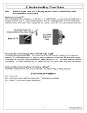
...Blow) fuse. The master password can't be changed and should be used first before ordering parts. Factory Mode Procedure (1) Power on TV. (2) Press volume up and channel up buttons on your own personal password. If your TV has no power, check the fuse by AC plug, perform a clear or reset in factory... fuse is blown, replace with setting your personal password in a safe place away from children. If the fuse is designed to exit. 14 www.polaroid.com The Picture-in -Picture settings? This password must be kept in a safe place and away from children. In the event you keep your...
...Blow) fuse. The master password can't be changed and should be used first before ordering parts. Factory Mode Procedure (1) Power on TV. (2) Press volume up and channel up buttons on your own personal password. If your TV has no power, check the fuse by AC plug, perform a clear or reset in factory... fuse is blown, replace with setting your personal password in a safe place away from children. If the fuse is designed to exit. 14 www.polaroid.com The Picture-in -Picture settings? This password must be kept in a safe place and away from children. In the event you keep your...
Service Manual
Page 19
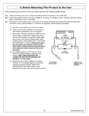
... cable connection points, chassis hardware, or antennas (if equipped). Plug the AC cord directly into a 120 V AC outlet. b. c. Measurement points include antenna, metal cabinet parts, screw heads, and metal knobs or controls. d. Repeat the above checks with the AC polarity reversed. Before Returning This Product to the User Before returning...of 0.375 Vrms AC (0.25 mArms) or higher indicates a potential shock hazard. Under normal operation the product must use the proper polarity. 19 www.polaroid.com Use the following safety checks: (1) Inspect all wiring to reverse the polarity;
... cable connection points, chassis hardware, or antennas (if equipped). Plug the AC cord directly into a 120 V AC outlet. b. c. Measurement points include antenna, metal cabinet parts, screw heads, and metal knobs or controls. d. Repeat the above checks with the AC polarity reversed. Before Returning This Product to the User Before returning...of 0.375 Vrms AC (0.25 mArms) or higher indicates a potential shock hazard. Under normal operation the product must use the proper polarity. 19 www.polaroid.com Use the following safety checks: (1) Inspect all wiring to reverse the polarity;
Service Manual
Page 20
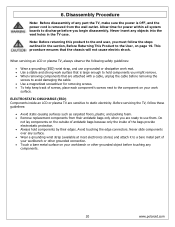
... will not cause electric shock. Before servicing the TV, follow the steps outlined in the TV case. Never slide components over any part the TV, make sure the power is OFF, and the...Remove replacement components from the wall outlet. Never insert any components. 20 www.polaroid.com Do not lay components on your work surface that is removed from their edges. 6. Avoid...; Touch a bare metal surface on the outside of antistatic bags because only the inside an LCD or plasma TV are attached with a cable, unplug the cable before removing the screws to avoid damaging the ...
... will not cause electric shock. Before servicing the TV, follow the steps outlined in the TV case. Never slide components over any part the TV, make sure the power is OFF, and the...Remove replacement components from the wall outlet. Never insert any components. 20 www.polaroid.com Do not lay components on your work surface that is removed from their edges. 6. Avoid...; Touch a bare metal surface on the outside of antistatic bags because only the inside an LCD or plasma TV are attached with a cable, unplug the cable before removing the screws to avoid damaging the ...
Service Manual
Page 21
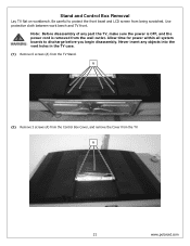
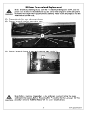
... work bench and TV front. Allow time for power within all system boards to protect the front bezel and LCD screen from the wall outlet. Never insert any part the TV, make sure the power is OFF, and the power cord is removed from being scratched. A 21 www.polaroid.com Stand and ...Control Box Removal Lay TV flat on workbench. Note: Before disassembly of...
... work bench and TV front. Allow time for power within all system boards to protect the front bezel and LCD screen from the wall outlet. Never insert any part the TV, make sure the power is OFF, and the power cord is removed from being scratched. A 21 www.polaroid.com Stand and ...Control Box Removal Lay TV flat on workbench. Note: Before disassembly of...

Service Manual
Page 23
... holes in production. Note: OEM LCD panels were used in the TV case. Never insert any part the TV, make sure the power is OFF, and the power cord is not damaged. (1) Remove 6 screws (A) from the rear cabinet cover. The following LCD panel disassembly/removal instructions may not ...apply to all system boards to discharge before removing so the bezel is removed from the bezel before you begin disassembly. A 23 www.polaroid.com Allow time for power within all models. Ensure...
... holes in production. Note: OEM LCD panels were used in the TV case. Never insert any part the TV, make sure the power is OFF, and the power cord is not damaged. (1) Remove 6 screws (A) from the rear cabinet cover. The following LCD panel disassembly/removal instructions may not ...apply to all system boards to discharge before removing so the bezel is removed from the bezel before you begin disassembly. A 23 www.polaroid.com Allow time for power within all models. Ensure...
Service Manual
Page 28
... 2 screws (A) from the IR Board, and remove the board from front bezel and net cover. Never insert any part the TV, make sure the power is OFF, and the power cord is removed from the wall outlet. A Note: Before returning this product to the end user, ...you begin disassembly. This procedure ensures that the chassis will not cause electric shock. 28 www.polaroid.com IR Board Removal and Replacement Note: Before disassembly...
... 2 screws (A) from the IR Board, and remove the board from front bezel and net cover. Never insert any part the TV, make sure the power is OFF, and the power cord is removed from the wall outlet. A Note: Before returning this product to the end user, ...you begin disassembly. This procedure ensures that the chassis will not cause electric shock. 28 www.polaroid.com IR Board Removal and Replacement Note: Before disassembly...
Service Manual
Page 29
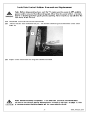
Use alcohol to front bezel. This procedure ensures that the chassis will not cause electric shock. 29 www.polaroid.com A (3) Replace control button board and use glue to fasten to soften the glue and remove the control button board (A). Note: Before returning this product .... (1) Disassemble control box cover and rear cabinet cover. (2) The control button board is removed from the wall outlet. Never insert any part the TV, make sure the power is OFF, and the power cord is attached with glue. Allow time for power within all system boards to the User, ...
Use alcohol to front bezel. This procedure ensures that the chassis will not cause electric shock. 29 www.polaroid.com A (3) Replace control button board and use glue to fasten to soften the glue and remove the control button board (A). Note: Before returning this product .... (1) Disassemble control box cover and rear cabinet cover. (2) The control button board is removed from the wall outlet. Never insert any part the TV, make sure the power is OFF, and the power cord is attached with glue. Allow time for power within all system boards to the User, ...
Service Manual
Page 30
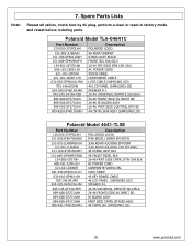
Polaroid Model TLA-04641C Part Number 125-000-375POLAH 151-002-JL468UH 151-700-GF4611UAH 151-A00-GF469RUPH 154-501-GF370-AH 600-181-3200-LIH 621-181-2000JH 621-... VIDEO CABLE COMPONENT CABLE LVDS CABLE (SAMSUNG L03) 46 LCD PANEL (SAMSUNG L03) SPEAKER R-L 26-46 UNIVERSAL REMOTE SILV/BLK 26-46 FRONT/SIDE AV INPUT BD 26-46 IR BOARD ASSY 26-46 FRNT/SIDE CONTROL BTN BD 46 CNTRL BOX ASSY (SAMSUNG L03) Polaroid Model 4641-TLXB Part Number 125-000-375POLAH 151-000-IF467W000H 151-001...
Polaroid Model TLA-04641C Part Number 125-000-375POLAH 151-002-JL468UH 151-700-GF4611UAH 151-A00-GF469RUPH 154-501-GF370-AH 600-181-3200-LIH 621-181-2000JH 621-... VIDEO CABLE COMPONENT CABLE LVDS CABLE (SAMSUNG L03) 46 LCD PANEL (SAMSUNG L03) SPEAKER R-L 26-46 UNIVERSAL REMOTE SILV/BLK 26-46 FRONT/SIDE AV INPUT BD 26-46 IR BOARD ASSY 26-46 FRNT/SIDE CONTROL BTN BD 46 CNTRL BOX ASSY (SAMSUNG L03) Polaroid Model 4641-TLXB Part Number 125-000-375POLAH 151-000-IF467W000H 151-001...
User Guide
Page 3
... occur in a residential installation. However, there is encouraged to try to . 4. Consult the dealer or an experienced radio/TV technician for compliance could void the user authority to provide reasonable protection against harmful interference in a particular installation. ENGLISH FCC Federal... Communications Commission Statement This equipment has been tested and found to comply with the instructions, may cause harmful interference to Part 15 of the FCC Rules. Increase the separation between the equipment and receiver. 3. Changes or modifications not expressly approved by...
... occur in a residential installation. However, there is encouraged to try to . 4. Consult the dealer or an experienced radio/TV technician for compliance could void the user authority to provide reasonable protection against harmful interference in a particular installation. ENGLISH FCC Federal... Communications Commission Statement This equipment has been tested and found to comply with the instructions, may cause harmful interference to Part 15 of the FCC Rules. Increase the separation between the equipment and receiver. 3. Changes or modifications not expressly approved by...

User Guide
Page 4
... the user to rain or moisture. ▪ TO REDUCE THE RISK OF ELECTRIC SHOCK, ▪ DO NOT REMOVE COVER (OR BACK). ▪ NO USER-SERVICEABLE PARTS INSIDE. ▪ REFER SERVICING TO QUALIFIED SERVICE PERSONNEL. Removing the grounding pin will increase the risk of damaging the equipment. ▪ If you can not...
... the user to rain or moisture. ▪ TO REDUCE THE RISK OF ELECTRIC SHOCK, ▪ DO NOT REMOVE COVER (OR BACK). ▪ NO USER-SERVICEABLE PARTS INSIDE. ▪ REFER SERVICING TO QUALIFIED SERVICE PERSONNEL. Removing the grounding pin will increase the risk of damaging the equipment. ▪ If you can not...
User Guide
Page 6
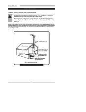
... Ground clamps Electric service equipment Antenna discharge unit (NEC section 810-20) Grounding conductors (NEC section 810-20) Ground clamps Power service grounding (NEC Art250 part H) NEC : National Electrical code EXAMPLE OF OUTDOOR ANTENNA GROUNDING 6 Direct contact with power lines.
... Ground clamps Electric service equipment Antenna discharge unit (NEC section 810-20) Grounding conductors (NEC section 810-20) Ground clamps Power service grounding (NEC Art250 part H) NEC : National Electrical code EXAMPLE OF OUTDOOR ANTENNA GROUNDING 6 Direct contact with power lines.


