
Service Manual
Page 1
... BRIDGEABLE FOUR-CHANNEL POWER AMPLIFIER GM-X434 GM-X334 X1R/UC,EW,ES ORDER NO. EXPLODED VIEWS AND PARTS LIST 2 3. GENERAL INFORMATION 20 7.1 IC 20 7.2 DISASSEMBLY 22 8. Haven 1087 Keetberglaan 1, 9120 Melsele, Belgium PIONEER ELECTRONICS ASIACENTRE PTE.LTD. 253 Alexandra Road, #04-01, Singapore 159936 C PIONEER ELECTRONIC CORPORATION 1999 K-ZZA. ELECTRICAL PARTS LIST 16 6. PIONEER ELECTRONIC [EUROPE...
... BRIDGEABLE FOUR-CHANNEL POWER AMPLIFIER GM-X434 GM-X334 X1R/UC,EW,ES ORDER NO. EXPLODED VIEWS AND PARTS LIST 2 3. GENERAL INFORMATION 20 7.1 IC 20 7.2 DISASSEMBLY 22 8. Haven 1087 Keetberglaan 1, 9120 Melsele, Belgium PIONEER ELECTRONICS ASIACENTRE PTE.LTD. 253 Alexandra Road, #04-01, Singapore 159936 C PIONEER ELECTRONIC CORPORATION 1999 K-ZZA. ELECTRICAL PARTS LIST 16 6. PIONEER ELECTRONIC [EUROPE...
Service Manual
Page 3
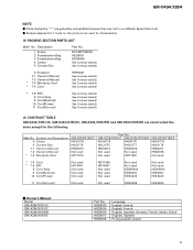
...HDE4455 - GM-X334/X1R/UC GM-X334/X1R/EW HHG0175 HHG0177 HHL0175 HHL0177 HRD0074 HRD0076 Not used Not used Not used HRY1087 GM-X334/X1R/ES HHG0178 HHL0178 HRD0077 HRD0078 Not used * 7-4 Card * 7-5 PRC 8 Cord Assy 9 Cord(Remote) 10 Cord(Power) Not ...Power) 11 Cord(Ground) See Contrast table(2) See Contrast table(2) See Contrast table(2) See Contrast table(2) See Contrast table(2) (2) CONTRAST TABLE GM-X434/X1R/UC, GM-X334/X1R/UC, GM-X334/X1R/EW and GM-X334/X1R/ES are used for the following: Mark No. Owner's Manual Model GM-X434/X1R/UC GM-X334/X1R/UC GM-X334/X1R/EW GM-X334...
...HDE4455 - GM-X334/X1R/UC GM-X334/X1R/EW HHG0175 HHG0177 HHL0175 HHL0177 HRD0074 HRD0076 Not used Not used Not used HRY1087 GM-X334/X1R/ES HHG0178 HHL0178 HRD0077 HRD0078 Not used * 7-4 Card * 7-5 PRC 8 Cord Assy 9 Cord(Remote) 10 Cord(Power) Not ...Power) 11 Cord(Ground) See Contrast table(2) See Contrast table(2) See Contrast table(2) See Contrast table(2) See Contrast table(2) (2) CONTRAST TABLE GM-X434/X1R/UC, GM-X334/X1R/UC, GM-X334/X1R/EW and GM-X334/X1R/ES are used for the following: Mark No. Owner's Manual Model GM-X434/X1R/UC GM-X334/X1R/UC GM-X334/X1R/EW GM-X334...

Service Manual
Page 23
... up , turn the gain control counter-clockwise. Input Select Switch For two-channel input, slide this switch to 12 dB. GM-X434,X334 23 For four-channel input, slide this switch to cut the verylow-frequency range because it is connected to the speaker output ...power indicator lights when the power is turned up , turn these controls clockwise. 8. OPERATIONS AND SPECIFICATIONS 8.1 OPERATIONS Setting the Unit Gain Control Adjusting the gain controls A and B will help match the output of the car stereo to the MIN position. • If you use one input plug, set to the Pioneer...
... up , turn the gain control counter-clockwise. Input Select Switch For two-channel input, slide this switch to 12 dB. GM-X434,X334 23 For four-channel input, slide this switch to cut the verylow-frequency range because it is connected to the speaker output ...power indicator lights when the power is turned up , turn these controls clockwise. 8. OPERATIONS AND SPECIFICATIONS 8.1 OPERATIONS Setting the Unit Gain Control Adjusting the gain controls A and B will help match the output of the car stereo to the MIN position. • If you use one input plug, set to the Pioneer...
Service Manual
Page 24
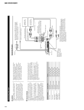
...may fail to work when it in a short-circuit through the ignition switch. After making all other equipment by cutting the insulation of the power supply wire to tap from the antenna, antenna cable and tuner. • Speakers to be connected to the amplifier should conform with a ... not have a system remote control terminal, connect the male terminal to the power terminal through the vehicle body. • Make sure that wires will always be connected to the auto-antenna relay control terminal. GM-X434,X334 24 Connecting the Unit CAUTION • Remove the negative (-) terminal of the...
...may fail to work when it in a short-circuit through the ignition switch. After making all other equipment by cutting the insulation of the power supply wire to tap from the antenna, antenna cable and tuner. • Speakers to be connected to the amplifier should conform with a ... not have a system remote control terminal, connect the male terminal to the power terminal through the vehicle body. • Make sure that wires will always be connected to the auto-antenna relay control terminal. GM-X434,X334 24 Connecting the Unit CAUTION • Remove the negative (-) terminal of the...

Service Manual
Page 25
... an audio signal is input. GM-X434,X334 8.2 SPECIFICATIONS - GM-X434/X1R/UC, GM-X334/X1R/UC, GM-X334/X1R/EW, GM-X334/X1R/ES Specifications Power source ...14.4 V DC (10.8 - 15.1 V allowable) Grounding system ...Negative type Current consumption ...18 A (at continuous power, 4 Ω) Average current ...× 250 (D) mm [8-1/2 (W) × 2-1/8 (H) × 9-7/8 (D) in] Weight ...3.0 kg (6.6 lbs) (Leads for wiring not included) Maximum power output ...60 W × 4 / 140 W × 2 (EIAJ) Continuous power output 30 W × 4 (at 14.4 V, 4 Ω, 20 - 20,000 Hz, 0.08% THD) 70 W × 2 (at ...
... an audio signal is input. GM-X434,X334 8.2 SPECIFICATIONS - GM-X434/X1R/UC, GM-X334/X1R/UC, GM-X334/X1R/EW, GM-X334/X1R/ES Specifications Power source ...14.4 V DC (10.8 - 15.1 V allowable) Grounding system ...Negative type Current consumption ...18 A (at continuous power, 4 Ω) Average current ...× 250 (D) mm [8-1/2 (W) × 2-1/8 (H) × 9-7/8 (D) in] Weight ...3.0 kg (6.6 lbs) (Leads for wiring not included) Maximum power output ...60 W × 4 / 140 W × 2 (EIAJ) Continuous power output 30 W × 4 (at 14.4 V, 4 Ω, 20 - 20,000 Hz, 0.08% THD) 70 W × 2 (at ...

