
Service Manual
Page 5
...28 Screw 29 Light Pipe Unit 30 Plate Unit Part No. Symbol and Description 6 Panel 7 Panel 9 Heat Sink 11 Amp Unit 15 Cord(CN831) GM-X434/X1R/UC HNB2409 HNB2415 HNR1514 HWH0082 HDE5817 Part No. HNC8117 HNC8119 PPZ30P060FZK HXB3450 See Contrast table(2) 31 Thermistor(TH951, 952)... table(2) See Contrast table(2) See Contrast table(2) (2) CONTRAST TABLE GM-X434/X1R/UC, GM-X334/X1R/UC, GM-X334/X1R/EW and GM-X334/X1R/ES are constructed the same except for the following: Mark No. GM-X334/X1R/UC GM-X334/X1R/EW HNB2408 HNB2403 HNB2410 HNB2413 HNR1512 HNR1512 HWH0081 HWH0079 HDE5817 Not...
...28 Screw 29 Light Pipe Unit 30 Plate Unit Part No. Symbol and Description 6 Panel 7 Panel 9 Heat Sink 11 Amp Unit 15 Cord(CN831) GM-X434/X1R/UC HNB2409 HNB2415 HNR1514 HWH0082 HDE5817 Part No. HNC8117 HNC8119 PPZ30P060FZK HXB3450 See Contrast table(2) 31 Thermistor(TH951, 952)... table(2) See Contrast table(2) See Contrast table(2) (2) CONTRAST TABLE GM-X434/X1R/UC, GM-X334/X1R/UC, GM-X334/X1R/EW and GM-X334/X1R/ES are constructed the same except for the following: Mark No. GM-X334/X1R/UC GM-X334/X1R/EW HNB2408 HNB2403 HNB2410 HNB2413 HNR1512 HNR1512 HWH0081 HWH0079 HDE5817 Not...

Service Manual
Page 12
PCB CONNECTION DIAGRAM 4.1 AMP UNIT A NOTE FOR PCB DIAGRAMS 1. The parts mounted on this PCB A AMP UNIT include all necessary parts for respective destinations, be sure to check with the schematic dia- Viewpoint of PCB diagrams Connector Capacitor SIDE A B P.C.Board Chip Part SIDE B C D A 12 1 2 3 4 For further information for several destination. gram. 2. 1 2 3 4 GM-X434,X334 4.
PCB CONNECTION DIAGRAM 4.1 AMP UNIT A NOTE FOR PCB DIAGRAMS 1. The parts mounted on this PCB A AMP UNIT include all necessary parts for respective destinations, be sure to check with the schematic dia- Viewpoint of PCB diagrams Connector Capacitor SIDE A B P.C.Board Chip Part SIDE B C D A 12 1 2 3 4 For further information for several destination. gram. 2. 1 2 3 4 GM-X434,X334 4.

Service Manual
Page 16
... Symbol and No.===Part Name Part No A Unit Number Unit Number Unit Number Unit Number Unit Name : HWH0082(GM-X434/X1R/UC) : HWH0081(GM-X334/X1R/UC) : HWH0079(GM-X334/X1R/EW) : HWH0080(GM-X334/X1R/ES) : Amp Unit =====Circuit Symbol and No.===Part Name Q 652 Q 653 Q 654 Q 655 Q 656 Transistor Transistor Transistor... CTF1007 CTH1218 CTT1090 CCX1013 CCX1013 CCX1035 CSH1029 CSH1029 CSH1042 See Contrast table CCS1241 CCS1240 See Contrast table CCS1241 HEK0025 16 GM-X434,X334 5. Parts whose parts numbers are omitted are subject to being not supplied. - ELECTRICAL PARTS LIST NOTES: -
... Symbol and No.===Part Name Part No A Unit Number Unit Number Unit Number Unit Number Unit Name : HWH0082(GM-X434/X1R/UC) : HWH0081(GM-X334/X1R/UC) : HWH0079(GM-X334/X1R/EW) : HWH0080(GM-X334/X1R/ES) : Amp Unit =====Circuit Symbol and No.===Part Name Q 652 Q 653 Q 654 Q 655 Q 656 Transistor Transistor Transistor... CTF1007 CTH1218 CTT1090 CCX1013 CCX1013 CCX1035 CSH1029 CSH1029 CSH1042 See Contrast table CCS1241 CCS1240 See Contrast table CCS1241 HEK0025 16 GM-X434,X334 5. Parts whose parts numbers are omitted are subject to being not supplied. - ELECTRICAL PARTS LIST NOTES: -

Service Manual
Page 20
... + + A OUTPUT 1 A -INPUT 2 A +INPUT 3 V- 4 B +INPUT 5 B -INPUT 6 B OUTPUT 7 V+ 8 20 ADJUSTMENT There is no information to be shown in this chapter. 7. GM-X434,X334 CONTRAST TABLE of AMP UNIT GM-X434/X1R/UC, GM-X334/X1R/UC, GM-X334/X1R/EW and GM-X334/X1R/ES are constructed the same except for the following: Symbol and Description S 951 Switch(BFC) VR 103 Volume...
... + + A OUTPUT 1 A -INPUT 2 A +INPUT 3 V- 4 B +INPUT 5 B -INPUT 6 B OUTPUT 7 V+ 8 20 ADJUSTMENT There is no information to be shown in this chapter. 7. GM-X434,X334 CONTRAST TABLE of AMP UNIT GM-X434/X1R/UC, GM-X334/X1R/UC, GM-X334/X1R/EW and GM-X334/X1R/ES are constructed the same except for the following: Symbol and Description S 951 Switch(BFC) VR 103 Volume...

Service Manual
Page 22
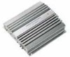
Sub Heat Sink Heat Sink Amp Unit Sub Heat Sink Fig.1 22 Alternately tighten them into the two holes marked with an arrow. Removing the Panel Unit(not shown) 1. GM-X434,X334 7.2 DIAGNOSIS 7.2.1 DISASSEMBLY - Removing the Amp Unit(Fig.1) Remove the twelve screws. Removing the Case(not shown) 1. Remove the six screws. 2. of screw and insert them little by little until the Sub Heat Sink separates from the Heat Sink. Remove the nine screws. 2. Remove the Case. - Use 2 pcs. Remove the two Panel Units. -
Sub Heat Sink Heat Sink Amp Unit Sub Heat Sink Fig.1 22 Alternately tighten them into the two holes marked with an arrow. Removing the Panel Unit(not shown) 1. GM-X434,X334 7.2 DIAGNOSIS 7.2.1 DISASSEMBLY - Removing the Amp Unit(Fig.1) Remove the twelve screws. Removing the Case(not shown) 1. Remove the six screws. 2. of screw and insert them little by little until the Sub Heat Sink separates from the Heat Sink. Remove the nine screws. 2. Remove the Case. - Use 2 pcs. Remove the two Panel Units. -


