Owner's Manual
Page 7
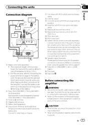
...terminal. Connecting the units Section 03 English Connection diagram 2 3 5 a 7 6 4 8 9 b c 1 e d i h j f g 1 Battery wire (sold separately) ! The female terminal can be separately fused at the amplifier, connect the battery wire terminal of the amplifier to metal body or ...the battery. 2 Fuse 100 A (GM-D8601) / 150 A (GM-D9601) (sold separately) Each amplifier must be connected to other connections at 100 A (GM-D8601) / 150 A (GM-D9601). 3 Positive (+) terminal 4 Negative (*) terminal 5 Battery (sold separately) 6 Ground wire, Terminal (sold sepa- g Speaker...
...terminal. Connecting the units Section 03 English Connection diagram 2 3 5 a 7 6 4 8 9 b c 1 e d i h j f g 1 Battery wire (sold separately) ! The female terminal can be separately fused at the amplifier, connect the battery wire terminal of the amplifier to metal body or ...the battery. 2 Fuse 100 A (GM-D8601) / 150 A (GM-D9601) (sold separately) Each amplifier must be connected to other connections at 100 A (GM-D8601) / 150 A (GM-D9601). 3 Positive (+) terminal 4 Negative (*) terminal 5 Battery (sold separately) 6 Ground wire, Terminal (sold sepa- g Speaker...


