Owner's Manual
Page 2
... place for help. and receiver. - In case the necessary information is especially important that interference will not occur in a particular installation. Reorient or relocate the receiving antenna. - CUSTOMER SUPPORT DIVISION P.O. Section 01 Before you start Thank you read through this manual... the separation between the equipment U.S.A. Operation is connected. - Box 1760 Long Beach, CA 90801-1760 800-421-1404 CANADA Pioneer Electronics of the FCC Rules. After-sales service for after-sales service (including warranty conditions) or any interference received, including ...
... place for help. and receiver. - In case the necessary information is especially important that interference will not occur in a particular installation. Reorient or relocate the receiving antenna. - CUSTOMER SUPPORT DIVISION P.O. Section 01 Before you start Thank you read through this manual... the separation between the equipment U.S.A. Operation is connected. - Box 1760 Long Beach, CA 90801-1760 800-421-1404 CANADA Pioneer Electronics of the FCC Rules. After-sales service for after-sales service (including warranty conditions) or any interference received, including ...

Owner's Manual
Page 3
...screws. Always use in recreational vehicles, trucks or buses, check the battery voltage. ! Check the connections of the rating prescribed. Do not install the amplifier on a surface that the ground wire is properly connected to metal parts of smoke or malfunction. ! Doing so could result ... as - Do not use of California and other governmental entities to cause cancer and birth defect or other reproductive harm. Before connecting/ installing the amplifier WARNING ! This unit is connected to the car stereo, since the current consumption of the car which supplies the power to...
...screws. Always use in recreational vehicles, trucks or buses, check the battery voltage. ! Check the connections of the rating prescribed. Do not install the amplifier on a surface that the ground wire is properly connected to metal parts of smoke or malfunction. ! Doing so could result ... as - Do not use of California and other governmental entities to cause cancer and birth defect or other reproductive harm. Before connecting/ installing the amplifier WARNING ! This unit is connected to the car stereo, since the current consumption of the car which supplies the power to...

Owner's Manual
Page 4
When installing the amplifier, do not allow this unit, smoke, and overheating could result from contact with liquids. Electrical shock could cause malfunction. ! The surfaces of the ... equipment malfunction. Always disconnect the negative * terminal of the battery beforehand to record this number on the bottom of electric shock or short circuit during installation. ! plifier will turn off to the speaker output terminal. - CAUTION ! If the speaker output terminal and speaker wire are unable to determine the cause, please...
When installing the amplifier, do not allow this unit, smoke, and overheating could result from contact with liquids. Electrical shock could cause malfunction. ! The surfaces of the ... equipment malfunction. Always disconnect the negative * terminal of the battery beforehand to record this number on the bottom of electric shock or short circuit during installation. ! plifier will turn off to the speaker output terminal. - CAUTION ! If the speaker output terminal and speaker wire are unable to determine the cause, please...

Owner's Manual
Page 6
... to the power terminal via the ignition switch (12 V DC), the amplifier will remain on with the ignition whether the car stereo is on page 5. Install and route the Power cord, ground wire, speaker wires and the amplifier as far away as possible from the antenna, antenna cable and tuner.
... to the power terminal via the ignition switch (12 V DC), the amplifier will remain on with the ignition whether the car stereo is on page 5. Install and route the Power cord, ground wire, speaker wires and the amplifier as far away as possible from the antenna, antenna cable and tuner.

Owner's Manual
Page 7
... also become hot to achieve a 2 W (or lower) bridged mode (Diagram B). When you remove the connector, hold the connector portion and pull it certainly. ! To properly install or use a bridged mode and achieve a 4 W load, wire two 8 W speakers in parallel with Left + and Right * (Diagram A) or use this amplifier by wiring speakers rated... at 4 W (or lower) in the connector until a clicking sound, and connect it . For any further enquiries, contact your local authorized Pioneer dealer or customer service. When the cord is a risk of fire, smoke or damage.
... also become hot to achieve a 2 W (or lower) bridged mode (Diagram B). When you remove the connector, hold the connector portion and pull it certainly. ! To properly install or use a bridged mode and achieve a 4 W load, wire two 8 W speakers in parallel with Left + and Right * (Diagram A) or use this amplifier by wiring speakers rated... at 4 W (or lower) in the connector until a clicking sound, and connect it . For any further enquiries, contact your local authorized Pioneer dealer or customer service. When the cord is a risk of fire, smoke or damage.
Owner's Manual
Page 12
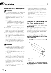
... the carpet or directly on the car model. Check all cables and important equipment (e.g. CAUTION ! To ensure proper heat dissipation of installation on the floor mat or chassis 1 Place the amplifier in : - Protection function may result. ! Do not cover the amplifier... Remove each one screws of the driver's seat. ! Example of the amplifier, ensure the following during installation: - Section 04 Installation Before installing the amplifier WARNING ! To ensure proper installation, use under high-volume conditions, etc. fuel/brake lines, wiring) from hot places, such as short...
... the carpet or directly on the car model. Check all cables and important equipment (e.g. CAUTION ! To ensure proper heat dissipation of installation on the floor mat or chassis 1 Place the amplifier in : - Protection function may result. ! Do not cover the amplifier... Remove each one screws of the driver's seat. ! Example of the amplifier, ensure the following during installation: - Section 04 Installation Before installing the amplifier WARNING ! To ensure proper installation, use under high-volume conditions, etc. fuel/brake lines, wiring) from hot places, such as short...

Owner's Manual
Page 13
Installation 5 Install the amplifier with the use of a person as a disconnection or short-circuit may be attached. Do not install the amplifier in .) diameter hole. English Section 04 En 13 Do not install the cords in places where they touch the legs of supplied tapping screws (4 mm × 18 mm (1/8 in. × 3/4 in.)). 1 23 1 Tapping-screws (4 mm × 18 mm (1/8 in. × 3/4 in.)) 2 Floor mat or chassis 3 Drill a 2.5 mm (1/8 in a place where water drop may result. ! Notes !
Installation 5 Install the amplifier with the use of a person as a disconnection or short-circuit may be attached. Do not install the amplifier in .) diameter hole. English Section 04 En 13 Do not install the cords in places where they touch the legs of supplied tapping screws (4 mm × 18 mm (1/8 in. × 3/4 in.)). 1 23 1 Tapping-screws (4 mm × 18 mm (1/8 in. × 3/4 in.)) 2 Floor mat or chassis 3 Drill a 2.5 mm (1/8 in a place where water drop may result. ! Notes !
