Service Manual
Page 4
SCHEMATIC DIAGRAM 12 3.1 OVERALL CONNECTION DIAGRAM(GUIDE PAGE) ....12 3.2 REMOTE CONTROL UNIT 18 B 4. PCB CONNECTION DIAGRAM 20 4.1 AMP UNIT 20 4.2 REMOTE CONTROL UNIT 24 5. ADJUSTMENT 28 7. 1 2 3 4 A CONTENTS SAFETY INFORMATION 2 1. OPERATIONS 32 C D E F 4 GM-7100M/XU/EW 1 2 3 4 ELECTRICAL PARTS LIST 25 6. SPECIFICATIONS 5 2. EXPLODED VIEWS AND PARTS LIST 6 2.1 PACKING 6 2.2 EXTERIOR 8 3. GENERAL INFORMATION 29 7.1 DIAGNOSIS 29 7.1.1 DISASSEMBLY 29 7.1.2 CONNECTOR FUNCTION DESCRIPTION ......31 8.
SCHEMATIC DIAGRAM 12 3.1 OVERALL CONNECTION DIAGRAM(GUIDE PAGE) ....12 3.2 REMOTE CONTROL UNIT 18 B 4. PCB CONNECTION DIAGRAM 20 4.1 AMP UNIT 20 4.2 REMOTE CONTROL UNIT 24 5. ADJUSTMENT 28 7. 1 2 3 4 A CONTENTS SAFETY INFORMATION 2 1. OPERATIONS 32 C D E F 4 GM-7100M/XU/EW 1 2 3 4 ELECTRICAL PARTS LIST 25 6. SPECIFICATIONS 5 2. EXPLODED VIEWS AND PARTS LIST 6 2.1 PACKING 6 2.2 EXTERIOR 8 3. GENERAL INFORMATION 29 7.1 DIAGNOSIS 29 7.1.1 DISASSEMBLY 29 7.1.2 CONNECTOR FUNCTION DESCRIPTION ......31 8.
Service Manual
Page 12
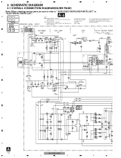
...refer to use parts of the part. 1 2 3 4 3. No differentiation is made between chip resistors and discrete resistors. SCHEMATIC DIAGRAM 3.1 OVERALL CONNECTION DIAGRAM(GUIDE PAGE) Note: When ordering service parts, be sure to " EXPLODED VIEWS AND PARTS LIST" or "ELECTRICAL PARTS LIST". ... 0dB or +12dB or +6dB ( or +9 +17.5dBs -15dBs B GAIN A BASS BOOST A B CN1351 C -0.8dB D E F A 12 GM-7100M/XU/EW 1 2 3 4 No differentiation is made between chip capacitors and discrete capacitors. ← ← Decimal points for resistor and capacitor fixed ...
...refer to use parts of the part. 1 2 3 4 3. No differentiation is made between chip resistors and discrete resistors. SCHEMATIC DIAGRAM 3.1 OVERALL CONNECTION DIAGRAM(GUIDE PAGE) Note: When ordering service parts, be sure to " EXPLODED VIEWS AND PARTS LIST" or "ELECTRICAL PARTS LIST". ... 0dB or +12dB or +6dB ( or +9 +17.5dBs -15dBs B GAIN A BASS BOOST A B CN1351 C -0.8dB D E F A 12 GM-7100M/XU/EW 1 2 3 4 No differentiation is made between chip capacitors and discrete capacitors. ← ← Decimal points for resistor and capacitor fixed ...

Service Manual
Page 20
PCB CONNECTION DIAGRAM 4.1 AMP UNIT A NOTE FOR PCB DIAGRAMS 1.The parts mounted on this PCB A AMP UNIT include all necessary parts for respective destinations, be sure to check with the schematic dia- gram. 2.Viewpoint of PCB diagrams Connector Capacitor SIDE A B SIDE B P.C.Board Chip Part SPEAKER OUTPUT SPEAKER OUTPUT C POWER SUPPLY D E F A 20 1 3 2 1 3 2 1 3 2 1 3 2 1 3 2 1 3 2 1 GM-7100M/XU/EW 2 3 4 1 2 3 4 4. For further information for several destination.
PCB CONNECTION DIAGRAM 4.1 AMP UNIT A NOTE FOR PCB DIAGRAMS 1.The parts mounted on this PCB A AMP UNIT include all necessary parts for respective destinations, be sure to check with the schematic dia- gram. 2.Viewpoint of PCB diagrams Connector Capacitor SIDE A B SIDE B P.C.Board Chip Part SPEAKER OUTPUT SPEAKER OUTPUT C POWER SUPPLY D E F A 20 1 3 2 1 3 2 1 3 2 1 3 2 1 3 2 1 3 2 1 GM-7100M/XU/EW 2 3 4 1 2 3 4 4. For further information for several destination.
Service Manual
Page 32
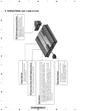
...stereo output level. • If you hear a beat while listening to 240 Hz. When using with an RCA equipped Pioneer car stereo with this power amplifier is too low, even when the volume of the car stereo used along with max...hear too much noise when using a small standard tip screwdriver. OPERATIONS (GM-7100M/XU/EW) 4 3 2 1 Bass Boost Control You can select a cut off frequency from 0, 6, 9 and 12 dB. 4 3 2 1 GM-7100M/XU/EW 32 F E Power Indicator The power indicator lights ... of 4 V or more, adjust level to the amplifier, see the "Connection Diagram" section. A 8.
...stereo output level. • If you hear a beat while listening to 240 Hz. When using with an RCA equipped Pioneer car stereo with this power amplifier is too low, even when the volume of the car stereo used along with max...hear too much noise when using a small standard tip screwdriver. OPERATIONS (GM-7100M/XU/EW) 4 3 2 1 Bass Boost Control You can select a cut off frequency from 0, 6, 9 and 12 dB. 4 3 2 1 GM-7100M/XU/EW 32 F E Power Indicator The power indicator lights ... of 4 V or more, adjust level to the amplifier, see the "Connection Diagram" section. A 8.

