
Service Manual
Page 2
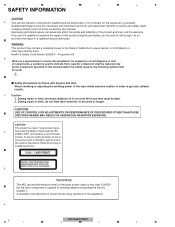
..., the following symbol shall be kept. 2. During repair or tests, do not view laser beam for those covered by the component specified in circuit diagrams or lists of the laser power output is less than CLASS 1 but the laser component is a class 1 laser product classi- CAUTION: USE OF CONTROLS OR ADJUSTMENTS OR PERFORMANCE OF PROCEDURES OTHER THAN THOSE...
..., the following symbol shall be kept. 2. During repair or tests, do not view laser beam for those covered by the component specified in circuit diagrams or lists of the laser power output is less than CLASS 1 but the laser component is a class 1 laser product classi- CAUTION: USE OF CONTROLS OR ADJUSTMENTS OR PERFORMANCE OF PROCEDURES OTHER THAN THOSE...
Service Manual
Page 4
......13 4. SCHEMATIC DIAGRAM...40 10.1 TUNER AMP UNIT (GUIDE PAGE) ...40 10.2 KEYBOARD UNIT...46 10.3 CD CORE UNIT (S11.6STD) ...48 10.4 KEYBOARD UNIT...50 10.5 BT UNIT ...52 10.6 WAVEFORMS ...54 11. EXPLODED VIEWS AND PARTS LIST...34 C 9.1 PACKING ...34 9.2 EXTERIOR...36 9.3 CD MECHANISM MODULE...38 10. DIAGNOSIS...17 B 5.1 OPERATIONAL FLOWCHART ...17 5.2 ERROR CODE LIST ...18 5.3 CONNECTOR FUNCTION DESCRIPTION 21 6. 1 2 3 4 CONTENTS SAFETY INFORMATION...2 1. SPECIFICATIONS ...8 2.1 SPECIFICATIONS ...8 2.2 DISC/CONTENT FORMAT...
......13 4. SCHEMATIC DIAGRAM...40 10.1 TUNER AMP UNIT (GUIDE PAGE) ...40 10.2 KEYBOARD UNIT...46 10.3 CD CORE UNIT (S11.6STD) ...48 10.4 KEYBOARD UNIT...50 10.5 BT UNIT ...52 10.6 WAVEFORMS ...54 11. EXPLODED VIEWS AND PARTS LIST...34 C 9.1 PACKING ...34 9.2 EXTERIOR...36 9.3 CD MECHANISM MODULE...38 10. DIAGNOSIS...17 B 5.1 OPERATIONAL FLOWCHART ...17 5.2 ERROR CODE LIST ...18 5.3 CONNECTOR FUNCTION DESCRIPTION 21 6. 1 2 3 4 CONTENTS SAFETY INFORMATION...2 1. SPECIFICATIONS ...8 2.1 SPECIFICATIONS ...8 2.2 DISC/CONTENT FORMAT...
Service Manual
Page 5
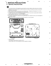
... grating. 5. B C D 7. Please replace IC671 when making the version upgrade of this manual. 2. After replacing the pickup unit, be damaged by following the safety instructions described in this product is stored in handling ICs. Be careful in IC671. area and a heat sink becomes hot areas. E F 5 DEH-64BT/XNUC 6 7 8 5 SERVICE PRECAUTIONS 1.1 SERVICE PRECAUTIONS A 1. You should keep the safety during power-on mode may damage...
... grating. 5. B C D 7. Please replace IC671 when making the version upgrade of this manual. 2. After replacing the pickup unit, be damaged by following the safety instructions described in this product is stored in handling ICs. Be careful in IC671. area and a heat sink becomes hot areas. E F 5 DEH-64BT/XNUC 6 7 8 5 SERVICE PRECAUTIONS 1.1 SERVICE PRECAUTIONS A 1. You should keep the safety during power-on mode may damage...
Service Manual
Page 8
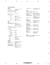
... 1.2 kg (2.6 lbs) C Audio Maximum power output ... 50 W × 4 Continuous power output 22 W × 4 (50 Hz to -24 dB Phase N. 1 2 3 4 2. MPEG-1 & 2 Audio Layer 3 WMA decoding format ..... nels driven) Load impedance 4 Ω (4 Ω to 8 Ω allowable) Preout maximum output level 2.0 V Tone controls: Bass Frequency .......... 100 Hz Gain 12 dB D Mid Frequency .......... 1 kHz Gain 12 dB Treble Frequency .......... 10 kHz Gain 12 dB Subwoofer (mono): Frequency 50 Hz/63...
... 1.2 kg (2.6 lbs) C Audio Maximum power output ... 50 W × 4 Continuous power output 22 W × 4 (50 Hz to -24 dB Phase N. 1 2 3 4 2. MPEG-1 & 2 Audio Layer 3 WMA decoding format ..... nels driven) Load impedance 4 Ω (4 Ω to 8 Ω allowable) Preout maximum output level 2.0 V Tone controls: Bass Frequency .......... 100 Hz Gain 12 dB D Mid Frequency .......... 1 kHz Gain 12 dB Treble Frequency .......... 10 kHz Gain 12 dB Subwoofer (mono): Frequency 50 Hz/63...
Service Manual
Page 9
... 12 dB Treble Bluetooth Version Bluetooth 3.0 certified Output power 4 dBm Maximum (Power class 2) Frequency 10 kHz Note Gain 12 dB Subwoofer (mono): Frequency 50 Hz/63 Hz/80 Hz/100 Hz/ Specifications and the design are subject to modifications without notice. 125 Hz Slope 18 dB/oct D Gain 6 dB to -24 dB Phase Normal/Reverse CD player System Compact disc audio system Usable discs Compact disc Signal...
... 12 dB Treble Bluetooth Version Bluetooth 3.0 certified Output power 4 dBm Maximum (Power class 2) Frequency 10 kHz Note Gain 12 dB Subwoofer (mono): Frequency 50 Hz/63 Hz/80 Hz/100 Hz/ Specifications and the design are subject to modifications without notice. 125 Hz Slope 18 dB/oct D Gain 6 dB to -24 dB Phase Normal/Reverse CD player System Compact disc audio system Usable discs Compact disc Signal...

Service Manual
Page 10
... Audio Maximum power output ... 50 W × 4 Continuous power output C 22 W × 4 (50 Hz to -noise ratio ......... 94 dB (1 kHz) (IEC-A network) Number of channels ........ 2 (stereo) E MP3 decoding format ...... ormal/Reverse CD player System Compact disc audio system Usable discs Compact disc Signal-to 15 000 Hz, 5 % THD, 4 Ω load, both chan- Linear PCM & MS ADPCM (Non-compressed) 2.2 DISC/CONTENT FORMAT USB USB standard specification USB 2.0 full speed Maximum current supply 1 A USB...
... Audio Maximum power output ... 50 W × 4 Continuous power output C 22 W × 4 (50 Hz to -noise ratio ......... 94 dB (1 kHz) (IEC-A network) Number of channels ........ 2 (stereo) E MP3 decoding format ...... ormal/Reverse CD player System Compact disc audio system Usable discs Compact disc Signal-to 15 000 Hz, 5 % THD, 4 Ω load, both chan- Linear PCM & MS ADPCM (Non-compressed) 2.2 DISC/CONTENT FORMAT USB USB standard specification USB 2.0 full speed Maximum current supply 1 A USB...
Service Manual
Page 14
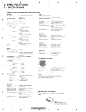
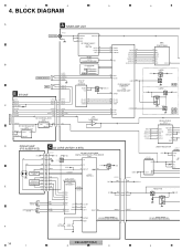
...DEH-64BT/XNUC 1 2 3 4 FOP 2 TRACKING ACT. 1 2 3 4 4. TOP 1 3 FOM 2 FOP 1 TOP ACTUATOR/ MOTOR DRIVER IC301 BD8223EFV PE5791A CN701 VDD VDD 9 CN701 9 VDD VDD3.3V E TOM 4 4 TOM TD,FD LD+ 14 14 LD+ 8 TKO+ 7 TKO10 FCO+ SD,MD VD VD 2 2 VD 1 1 MECHA VD Q751 Q752 B.UP 9 FCO- BLOCK DIAGRAM A A TUNER AMP UNIT ANTENNA JA401 1 2,3 B WIRED REMOTE...RESET IC651 1 S-80827CNMC-B8M FLASH ROM IC671 A B :PEB009A8 C :PEB008A8 D E F :PEB029A8 iPod... BTRST 4 DIMMER DAC IC231 ...UNIT (P10.6)(SERVICE) C CD CORE UNIT(S11.6 STD) USB5V REGULATOR IC501 BD9008 CN101 RF AMP...
...DEH-64BT/XNUC 1 2 3 4 FOP 2 TRACKING ACT. 1 2 3 4 4. TOP 1 3 FOM 2 FOP 1 TOP ACTUATOR/ MOTOR DRIVER IC301 BD8223EFV PE5791A CN701 VDD VDD 9 CN701 9 VDD VDD3.3V E TOM 4 4 TOM TD,FD LD+ 14 14 LD+ 8 TKO+ 7 TKO10 FCO+ SD,MD VD VD 2 2 VD 1 1 MECHA VD Q751 Q752 B.UP 9 FCO- BLOCK DIAGRAM A A TUNER AMP UNIT ANTENNA JA401 1 2,3 B WIRED REMOTE...RESET IC651 1 S-80827CNMC-B8M FLASH ROM IC671 A B :PEB009A8 C :PEB008A8 D E F :PEB029A8 iPod... BTRST 4 DIMMER DAC IC231 ...UNIT (P10.6)(SERVICE) C CD CORE UNIT(S11.6 STD) USB5V REGULATOR IC501 BD9008 CN101 RF AMP...

Service Manual
Page 18
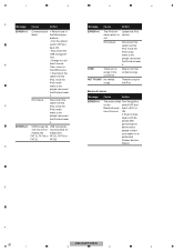
... repair work in servicing. (1) DISPLAY METHOD If "0xFD" error mode is displayed in CD MODE (CD MODE area for ejection Disc could not be ejected even after disc turning had been retried. --> A foreign object inserted in the mechanism; 1 2 3 4 5.2 ERROR CODE LIST ERROR CODES A If a CD memory device is inoperable, or operation of such media is stopped by an error, the error mode is established and a cause of the error is displayed by the equipment manufacturer. 8-digit display ERROR...
... repair work in servicing. (1) DISPLAY METHOD If "0xFD" error mode is displayed in CD MODE (CD MODE area for ejection Disc could not be ejected even after disc turning had been retried. --> A foreign object inserted in the mechanism; 1 2 3 4 5.2 ERROR CODE LIST ERROR CODES A If a CD memory device is inoperable, or operation of such media is stopped by an error, the error mode is established and a cause of the error is displayed by the equipment manufacturer. 8-digit display ERROR...
Service Manual
Page 19
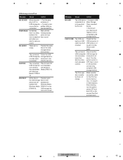
... replace it . Check that the start of playback hear sound. USB cable is patible USB stor- The connected Disconnect the SKIPPED PROTECT The connected Follow the USB USB storage de- or ON and then connect only compliant USB C storage devices. E F 5 DEH-64BT/XNUC 6 7 8 19 between the pears and you CHECK USB The USB con- cable has short- Transfer the audio files to hear any nector or USB USB connector or B sound. storage device...
... replace it . Check that the start of playback hear sound. USB cable is patible USB stor- The connected Disconnect the SKIPPED PROTECT The connected Follow the USB USB storage de- or ON and then connect only compliant USB C storage devices. E F 5 DEH-64BT/XNUC 6 7 8 19 between the pears and you CHECK USB The USB con- cable has short- Transfer the audio files to hear any nector or USB USB connector or B sound. storage device...
Service Manual
Page 20
iPod failure. played, reconnect the iPod and reset it . vice should be for the switch OFF and Bluetooth mod- Once the iPod's main menu is displayed, reconnect the iPod and reset it . Transfer songs to the USB source. Disconnect the cable from the iPod. played, reconnect the iPod and reset it. ERROR-23 USB storage de- Bluetooth device Message Cause Action ERROR-10 The power failed Turn the ignition for - If the error mes- erations. -Turn the...
iPod failure. played, reconnect the iPod and reset it . vice should be for the switch OFF and Bluetooth mod- Once the iPod's main menu is displayed, reconnect the iPod and reset it . Transfer songs to the USB source. Disconnect the cable from the iPod. played, reconnect the iPod and reset it. ERROR-23 USB storage de- Bluetooth device Message Cause Action ERROR-10 The power failed Turn the ignition for - If the error mes- erations. -Turn the...
Service Manual
Page 23
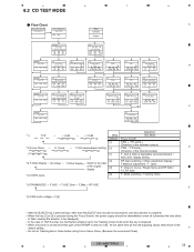
Curve t F EQ measurement setting [ Flow Chart A [4]+[6]->BUP+ACC ON Test Mode IN [CD] or [SOURCE] Source ON [Key] Contents TRK MIN Display [BAND] Power On (T.Offset is adjusted) TRK MIN SEC 00 00 00 [2] RF AMP *1 Gain switching TRK MIN SEC GG GG GG [BAND] [3] [6] [1] [>] [] CRG + 8X 8X 8X or 9X 9X 9X [] CRG/TR Jump + *4 TRK MIN SEC ?tr ?min ?sec [] CRG + / TR Jump + (Direction of the external surface) *2) Focus Close t S. 5 6 7 8 6.2 CD TEST MODE -
Curve t F EQ measurement setting [ Flow Chart A [4]+[6]->BUP+ACC ON Test Mode IN [CD] or [SOURCE] Source ON [Key] Contents TRK MIN Display [BAND] Power On (T.Offset is adjusted) TRK MIN SEC 00 00 00 [2] RF AMP *1 Gain switching TRK MIN SEC GG GG GG [BAND] [3] [6] [1] [>] [] CRG + 8X 8X 8X or 9X 9X 9X [] CRG/TR Jump + *4 TRK MIN SEC ?tr ?min ?sec [] CRG + / TR Jump + (Direction of the external surface) *2) Focus Close t S. 5 6 7 8 6.2 CD TEST MODE -
Service Manual
Page 25
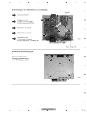
Tuner Amp Unit C D Fig.6 E F 5 DEH-64BT/XNUC 6 7 8 25 Removing the BT Unit and Tuner Amp Unit (Fig.5) 1 Disconnect the FFC. Attention of removing (Fig.6) Don't remove this screws excluding the dismantlement of the CD Mechanism Module. 5 6 7 8 - Straighten the tabs 3 2 at three locations indicated and then remove the BT Unit. 3 Remove the two screws. 4 Remove the two screws. 4 Straighten the tabs 5 at two locations indicated and then remove the Tuner Amp Unit. 5 3 1 4 BT Unit 2 2 2 5 A B Fig.5 -
Tuner Amp Unit C D Fig.6 E F 5 DEH-64BT/XNUC 6 7 8 25 Removing the BT Unit and Tuner Amp Unit (Fig.5) 1 Disconnect the FFC. Attention of removing (Fig.6) Don't remove this screws excluding the dismantlement of the CD Mechanism Module. 5 6 7 8 - Straighten the tabs 3 2 at three locations indicated and then remove the BT Unit. 3 Remove the two screws. 4 Remove the two screws. 4 Straighten the tabs 5 at two locations indicated and then remove the Tuner Amp Unit. 5 3 1 4 BT Unit 2 2 2 5 A B Fig.5 -
Service Manual
Page 26
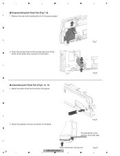
B 2. Assembling the Panel Part (Fig.9, 10, 11) 1. Attach the spring to the groove. Press the upside hook and the bottom side hook of the spring is set to this side. C - Fig.9 F 26 1 The bended tip of the button at the same time, and pull out the button. Remove the arm while bending the rib of the panel. D 4 Fig.7 Fig.8 E 2. DEH-64BT/XNUC 2 3 Fig.10 4 Hitch the spring to the arm as shown in the figure. Disassembling the Panel Part (Fig.7, 8) A 1. 1 2 3 - Attach the button from the front side of the panel upward.
B 2. Assembling the Panel Part (Fig.9, 10, 11) 1. Attach the spring to the groove. Press the upside hook and the bottom side hook of the spring is set to this side. C - Fig.9 F 26 1 The bended tip of the button at the same time, and pull out the button. Remove the arm while bending the rib of the panel. D 4 Fig.7 Fig.8 E 2. DEH-64BT/XNUC 2 3 Fig.10 4 Hitch the spring to the arm as shown in the figure. Disassembling the Panel Part (Fig.7, 8) A 1. 1 2 3 - Attach the button from the front side of the panel upward.
Service Manual
Page 29
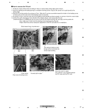
...outer end of the chassis (Fig 4), and remove the PU unit. (Cautions) When re-installing the PU, be sure to disengage it from Part B of the feeding screw is loosened. 4. Lift the PU unit to first nip the chassis and the PU unit (Fig 4) at the position A as ... Please follow the service manual for adjustment of the feeding screw laterally and then upward, to remove the PU unit 1. Slide toward the holder in Fig 1. E F 5 DEH-64BT/XNUC 6 7 8 29 Create an empty-clamp state according to "How to a tentative hooking portion (Fig 2b). Outer holder Rear end of feeding ...
...outer end of the chassis (Fig 4), and remove the PU unit. (Cautions) When re-installing the PU, be sure to disengage it from Part B of the feeding screw is loosened. 4. Lift the PU unit to first nip the chassis and the PU unit (Fig 4) at the position A as ... Please follow the service manual for adjustment of the feeding screw laterally and then upward, to remove the PU unit 1. Slide toward the holder in Fig 1. E F 5 DEH-64BT/XNUC 6 7 8 29 Create an empty-clamp state according to "How to a tentative hooking portion (Fig 2b). Outer holder Rear end of feeding ...
Service Manual
Page 30
... set to 0 dB, and the auto-adjustment values are easy to protect the actuator from the test mode. c. If you should mistakenly short the REFO1 with the GND when connecting the (-) probe of measuring instruments. When the power is turned off the ACC and back up the REFO1 with the GND during adjustment. 1 2 3 4 8. To avoid such problems: a. b. b. In the test mode...
... set to 0 dB, and the auto-adjustment values are easy to protect the actuator from the test mode. c. If you should mistakenly short the REFO1 with the GND when connecting the (-) probe of measuring instruments. When the power is turned off the ACC and back up the REFO1 with the GND during adjustment. 1 2 3 4 8. To avoid such problems: a. b. b. In the test mode...

Service Manual
Page 35
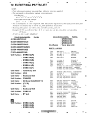
... used Not used 20-1 Owner's Manual QRD3096 QRD3096 QRD3096 Not used QRD3097 QRB3193 20-2 Quick Start Guide Not used Not used Not used QRD3094 Not used Not used 20-3 Installation Manual Not used Not used Not used QRD3095 Not used Not used C * 20-4 Warranty Card QRY3001 QRY3001 QRY3001 CRY1316 Not used CRY1304 * 20-5 Caution Card Not used Not used Not used QRP3009 Not used Not used * 20-6 Service Network Not used Not used Not used Not used Not used CRY1305 Owner's Manual,Installation Manual Part...
... used Not used 20-1 Owner's Manual QRD3096 QRD3096 QRD3096 Not used QRD3097 QRB3193 20-2 Quick Start Guide Not used Not used Not used QRD3094 Not used Not used 20-3 Installation Manual Not used Not used Not used QRD3095 Not used Not used C * 20-4 Warranty Card QRY3001 QRY3001 QRY3001 CRY1316 Not used CRY1304 * 20-5 Caution Card Not used Not used Not used QRP3009 Not used Not used * 20-6 Service Network Not used Not used Not used Not used Not used CRY1305 Owner's Manual,Installation Manual Part...
Service Manual
Page 40
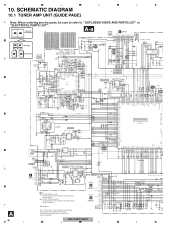
SCHEMATIC DIAGRAM 10.1 TUNER AMP UNIT (GUIDE PAGE) A Note: When ordering service parts, be sure to " EXPLODED VIEWS AND PARTS LIST" or "ELECTRICAL PARTS LIST". NM : No Mount The > mark found on some component parts...DEH-64BT/XNUC 1 2 3 4 Large size A-a A-b SCH diagram...3 A-a A-b Detailed page ANTENNA AM(30%) -15 dB&#... FLASH ...107 106 R504 12k DIMMER 6 VCC1 5 VSS1...RESET VDD4 DGND1 DATA BCLK LRCK PGND WAIT R716 220 1 VD 2 VD 3 /CDSRQ 4 /CDSTBY 5 SCL 6 SKIP 7 SDA 8 RESET...MODE USBU USBU USBA USBA USBAP USBAP REF USBD USBD V USBDP USBDP AS USB USB...Phone: -6.93 dBs BT MOD BT Audio...
SCHEMATIC DIAGRAM 10.1 TUNER AMP UNIT (GUIDE PAGE) A Note: When ordering service parts, be sure to " EXPLODED VIEWS AND PARTS LIST" or "ELECTRICAL PARTS LIST". NM : No Mount The > mark found on some component parts...DEH-64BT/XNUC 1 2 3 4 Large size A-a A-b SCH diagram...3 A-a A-b Detailed page ANTENNA AM(30%) -15 dB&#... FLASH ...107 106 R504 12k DIMMER 6 VCC1 5 VSS1...RESET VDD4 DGND1 DATA BCLK LRCK PGND WAIT R716 220 1 VD 2 VD 3 /CDSRQ 4 /CDSTBY 5 SCL 6 SKIP 7 SDA 8 RESET...MODE USBU USBU USBA USBA USBAP USBAP REF USBD USBD V USBDP USBDP AS USB USB...Phone: -6.93 dBs BT MOD BT Audio...

Service Manual
Page 41
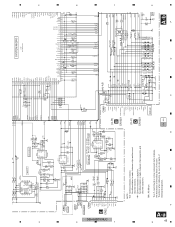
... BT Phone:+5.2 dBs BT Audio:+5.2 dBs E-VOL output FM(30%): -5.9 dBs AM(30%): -5.9 dBs FM(30%) (EW5): -1.9 dBs AM(30%) (EW5): -1.9 dBs AUX:+10.3 dBs CD/USB:+10.3 dBs BT Phone:+10.2 dBs BT Audio:+10.2 dBs RCA PLch C251 CCG1201-A 4.7u R251 820 MUTE 1 Q251 6 C252 PRch CCG1201-A 4.7u FLch C253 4.7u CCG1201-A R252 820 R253 820 5 2 4 3 A TUNER AMP UNIT...
... BT Phone:+5.2 dBs BT Audio:+5.2 dBs E-VOL output FM(30%): -5.9 dBs AM(30%): -5.9 dBs FM(30%) (EW5): -1.9 dBs AM(30%) (EW5): -1.9 dBs AUX:+10.3 dBs CD/USB:+10.3 dBs BT Phone:+10.2 dBs BT Audio:+10.2 dBs RCA PLch C251 CCG1201-A 4.7u R251 820 MUTE 1 Q251 6 C252 PRch CCG1201-A 4.7u FLch C253 4.7u CCG1201-A R252 820 R253 820 5 2 4 3 A TUNER AMP UNIT...
Service Manual
Page 45
... (C~F) D CN1821 CN801 DSENS CKS6288 C818 DSENS AUXL SOURCE AUXR AUXGND 0.1u/16 20 R818 2.2k 19... SYNC FLG MUTE VST VDT DPDT KYDT VCK BTTX BTRX C606 0.1u/10 5 VSS1 DIMMER 6 VCC1 ...only A,B only A,B GND SWV GND A-b A 8 7 6 5 8 45 7 6 5 DEH-64BT/XNUC A-a F E C 0.1 R 4 GND MODE1/SPI_nSS I2C_SCL/SPI_SIMO I2C_SDA/SPI_SOMI R552 10k...NC11 NC12 19 NC13 20 ipod CP 1 NC1 NC2 VCC nRESET 3 2 4 5...10 C513 NM GND R892 1k KEYD2 KEYAD2 R891 1k BT Phone: -6.93 dBs BT MOD BT Audio: -6.93 dBs LPF C968 470p/50 R969 10k IC961 NJM4558MD...replacing, be sure to use parts of the...
... (C~F) D CN1821 CN801 DSENS CKS6288 C818 DSENS AUXL SOURCE AUXR AUXGND 0.1u/16 20 R818 2.2k 19... SYNC FLG MUTE VST VDT DPDT KYDT VCK BTTX BTRX C606 0.1u/10 5 VSS1 DIMMER 6 VCC1 ...only A,B only A,B GND SWV GND A-b A 8 7 6 5 8 45 7 6 5 DEH-64BT/XNUC A-a F E C 0.1 R 4 GND MODE1/SPI_nSS I2C_SCL/SPI_SIMO I2C_SDA/SPI_SOMI R552 10k...NC11 NC12 19 NC13 20 ipod CP 1 NC1 NC2 VCC nRESET 3 2 4 5...10 C513 NM GND R892 1k KEYD2 KEYAD2 R891 1k BT Phone: -6.93 dBs BT MOD BT Audio: -6.93 dBs LPF C968 470p/50 R969 10k IC961 NJM4558MD...replacing, be sure to use parts of the...
Service Manual
Page 67
...replacing, be sure to being not supplied. B:DEH-6400BT/XNUC C:DEH-5400BT/XNUC D:DEH-4400BT/XNEW5 E:DEH-4450BT/XNES F:DEH-4490BT/XNID Unit Number : QWM3362(A) : QWM3300(B) Circuit Symbol and No. Meaning of the corresponding B PC board. A The part numbers shown below indicate chip components. Part No. : QWM3298(D) : QWM3301(E) : QWM3302(F) Unit Name : Tuner Amp Unit...81) Diode RB551V-30 5 DEH-64BT/XNUC 6 7 8 67 ELECTRICAL PARTS LIST NOTE: Parts whose parts numbers are omitted are subject to use parts of the part. The > mark found on the point (face A, 91 of x-axis, ...
...replacing, be sure to being not supplied. B:DEH-6400BT/XNUC C:DEH-5400BT/XNUC D:DEH-4400BT/XNEW5 E:DEH-4450BT/XNES F:DEH-4490BT/XNID Unit Number : QWM3362(A) : QWM3300(B) Circuit Symbol and No. Meaning of the corresponding B PC board. A The part numbers shown below indicate chip components. Part No. : QWM3298(D) : QWM3301(E) : QWM3302(F) Unit Name : Tuner Amp Unit...81) Diode RB551V-30 5 DEH-64BT/XNUC 6 7 8 67 ELECTRICAL PARTS LIST NOTE: Parts whose parts numbers are omitted are subject to use parts of the part. The > mark found on the point (face A, 91 of x-axis, ...


