
Installation Instructions
Page 1
FV-05-11VKS1 FV-05-11VK1 FV-11-15VK1 FV-05-11VKS1 FV-05-11VK1 FV-11-15VK1 Contents GENERAL SAFETY INFORMATION 2-3 PLEASE READ PRIOR TO INSTALLING THIS FAN 4 DESCRIPTION 4 UNPACKING 4 SUPPLIED ACCESSORIES 5 DIMENSIONS 5 WIRING DIAGRAM 5 FEATURE 5-6 INDICATION (PLUG 'N PLAY FUNCTION DEVICES) 6-7 DESCRIPTION FOR NIGHT LIGHT MODULE 7 MOTION (PLUG 'N PLAY FUNCTION DEVICES) 7 INSTALLATION (PLUG 'N PLAY FUNCTION DEVICES) 8 INSTALLATION (NEW CONSTRUCTION) 8-10 INSTALLATION (RETROFIT) 10 MAINTENANCE (CLEANING) 11...
FV-05-11VKS1 FV-05-11VK1 FV-11-15VK1 FV-05-11VKS1 FV-05-11VK1 FV-11-15VK1 Contents GENERAL SAFETY INFORMATION 2-3 PLEASE READ PRIOR TO INSTALLING THIS FAN 4 DESCRIPTION 4 UNPACKING 4 SUPPLIED ACCESSORIES 5 DIMENSIONS 5 WIRING DIAGRAM 5 FEATURE 5-6 INDICATION (PLUG 'N PLAY FUNCTION DEVICES) 6-7 DESCRIPTION FOR NIGHT LIGHT MODULE 7 MOTION (PLUG 'N PLAY FUNCTION DEVICES) 7 INSTALLATION (PLUG 'N PLAY FUNCTION DEVICES) 8 INSTALLATION (NEW CONSTRUCTION) 8-10 INSTALLATION (RETROFIT) 10 MAINTENANCE (CLEANING) 11...

Installation Instructions
Page 2
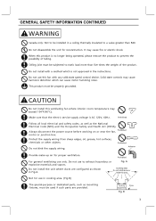
... with the grounding terminal. CAUTION Denotes a hazard that must be marked as a tag, to operate the unit safely. This symbol is to be installed over a tub or shower, it must not be connected to a GFCI(Ground Fault Circuit Interrupter) - This symbol is used to alert users to... electric shock or injury to persons, observe the following safety precautions. This symbol is used to alert users not to disassemble the equipment. Installation work and electrical wiring must be done by the manufacturer. For Your Safety To reduce the risk of injury, loss of life, electric shock...
... with the grounding terminal. CAUTION Denotes a hazard that must be marked as a tag, to operate the unit safely. This symbol is to be installed over a tub or shower, it must not be connected to a GFCI(Ground Fault Circuit Interrupter) - This symbol is used to alert users to... electric shock or injury to persons, observe the following safety precautions. This symbol is used to alert users not to disassemble the equipment. Installation work and electrical wiring must be done by the manufacturer. For Your Safety To reduce the risk of injury, loss of life, electric shock...
Installation Instructions
Page 3
...motor or junction box. Do not use to static load more than R40. Do not disassemble the unit for proper ventilation. Do not install with any solid-state speed control device. Make sure that the electric service supply voltage is not approved in the instructions. Protect the supply...ducts are configured as the National Electrical Code (NEC) and the Occupation Safety and Health Act (OSHA). WARNING Canada only: Not to be installed in a ceiling thermally insulated to prevent the possibility of the product. It may exceed 104°F(40°C). When this ventilating fan where interior...
...motor or junction box. Do not use to static load more than R40. Do not disassemble the unit for proper ventilation. Do not install with any solid-state speed control device. Make sure that the electric service supply voltage is not approved in the instructions. Protect the supply...ducts are configured as the National Electrical Code (NEC) and the Occupation Safety and Health Act (OSHA). WARNING Canada only: Not to be installed in a ceiling thermally insulated to prevent the possibility of the product. It may exceed 104°F(40°C). When this ventilating fan where interior...

Installation Instructions
Page 4
... to run continuously at low CFM levels 24 hours a day. FV-11-15VK1: 0, 50, 60, 70, 80, 90, 100, 110, 120 CFM). CustomVent Multi-Speed module (Lower Setting). The setting is crucial that the installer pre-set lower level (FV-05-11VKS1 and FV-05-11VK1: 0, 30, 40, 50, 60, 70, 80, 90,... 100 CFM; PLEASE READ PRIOR TO INSTALLING THIS FAN Spot and Continuous Ventilation: These fans are built to the chart below ...
... to run continuously at low CFM levels 24 hours a day. FV-11-15VK1: 0, 50, 60, 70, 80, 90, 100, 110, 120 CFM). CustomVent Multi-Speed module (Lower Setting). The setting is crucial that the installer pre-set lower level (FV-05-11VKS1 and FV-05-11VK1: 0, 30, 40, 50, 60, 70, 80, 90,... 100 CFM; PLEASE READ PRIOR TO INSTALLING THIS FAN Spot and Continuous Ventilation: These fans are built to the chart below ...
Installation Instructions
Page 5
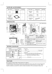
... 4 1 tapping screws -ST4.2X20) Part name Warranty sheet Installation instructions Self-drilling screw Appearance Quantity 1 2 4 DIMENSIONS 7/8 (22.5) 1 (26) 4 5/8 (116) 10 FV-05-11VK1 FV-11-15VK1 Unit: inches (mm) FV-11-15VK1 12 1/8 (307) 10 1/4 (260) 3 7/8 (98) 5 7/8 (148) 5 7/8 (148) 13 (330) 3 1/4 (81) 3 1/2 (88) FV-05-11VKS1 13 (330) 10 1/4 (260) 3 7/8 (100) FV-11-15VK1 12 11 7 3/8 (190) 6 3/8 (163) 11...
... 4 1 tapping screws -ST4.2X20) Part name Warranty sheet Installation instructions Self-drilling screw Appearance Quantity 1 2 4 DIMENSIONS 7/8 (22.5) 1 (26) 4 5/8 (116) 10 FV-05-11VK1 FV-11-15VK1 Unit: inches (mm) FV-11-15VK1 12 1/8 (307) 10 1/4 (260) 3 7/8 (98) 5 7/8 (148) 5 7/8 (148) 13 (330) 3 1/4 (81) 3 1/2 (88) FV-05-11VKS1 13 (330) 10 1/4 (260) 3 7/8 (100) FV-11-15VK1 12 11 7 3/8 (190) 6 3/8 (163) 11...
Installation Instructions
Page 6
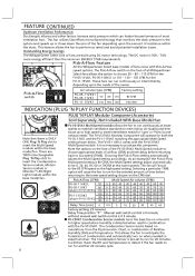
... Sensor module turns the base fan on when needed to choose 50 - 80 - 110 CFM for the FV-05-11VK1, FV-05-11VKS1 or 110 - 130 - 150 CFM for 'Spot' or 'Point Source' exhaust needs. This fan... or 70CFM at lower speeds to maintain ventilation standards to run for both the FV-05-11VK1 and the FV-11-15VK1 matching the appropriate Multi-Speed setting shown below. The FV-VS15VK1 Modular Component will then check the RH and Temperature to detect if the ...ONLY ONE Plug 'N Play slot to the 80 CFM speed as rated and avoid potential installation issues. The FV-05-11VKS1 comes with the...
... Sensor module turns the base fan on when needed to choose 50 - 80 - 110 CFM for the FV-05-11VK1, FV-05-11VKS1 or 110 - 130 - 150 CFM for 'Spot' or 'Point Source' exhaust needs. This fan... or 70CFM at lower speeds to maintain ventilation standards to run for both the FV-05-11VK1 and the FV-11-15VK1 matching the appropriate Multi-Speed setting shown below. The FV-VS15VK1 Modular Component will then check the RH and Temperature to detect if the ...ONLY ONE Plug 'N Play slot to the 80 CFM speed as rated and avoid potential installation issues. The FV-05-11VKS1 comes with the...

Installation Instructions
Page 8
... You can purchase the specified Plug 'N Play devices that are explained on it. (Fig.2) 3. Remove the connector cover from damper and adaptor before installation. (Fig.1) IMPORTANT: Remove the tape from position , 2 or 3 . 2. Remove junction box cover and secure conduit or stress relief to the ... foil tape. Squeeze, insert and release the tabs on it with Multi-Speed module (model FV-05-11VKS1 already have this control installed), position 2 and 3 can be used for positioning, install the Flex-Z FastTM bracket to joists by drilling the other 2 tapping screws which have been ...
... You can purchase the specified Plug 'N Play devices that are explained on it. (Fig.2) 3. Remove the connector cover from damper and adaptor before installation. (Fig.1) IMPORTANT: Remove the tape from position , 2 or 3 . 2. Remove junction box cover and secure conduit or stress relief to the ... foil tape. Squeeze, insert and release the tabs on it with Multi-Speed module (model FV-05-11VKS1 already have this control installed), position 2 and 3 can be used for positioning, install the Flex-Z FastTM bracket to joists by drilling the other 2 tapping screws which have been ...
Installation Instructions
Page 9
... for plug-in the specified devices as the National Electrical Code (NEC). Remove the tapes from louver and springs before installation. (Fig.8) IMPORTANT: Replace the sensor cover before the installation (only for FV-MSVK1) into the clasp (Fig.9). Ceiling hole should be aligned with caulk or other sealant to wiring diagram on page...
... for plug-in the specified devices as the National Electrical Code (NEC). Remove the tapes from louver and springs before installation. (Fig.8) IMPORTANT: Replace the sensor cover before the installation (only for FV-MSVK1) into the clasp (Fig.9). Ceiling hole should be aligned with caulk or other sealant to wiring diagram on page...

Installation Instructions
Page 10
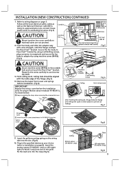
...Ceiling 14. Ceiling Machine screw (M4X6) Flange 2 Self-drilling screws (Fix the flange and Flex-Z FastTM bracket through the ceiling) Fig.14 10 INSTALLATION (NEW CONSTRUCTION) CONTINUED 13. Secure the Flex-Z FastTM bracket to the suitable hole and not touch the Flex-Z FastTM bracket. Follow the step 10... 4 tapping screws (ST4.2x20) which have been fixed on page 9 to 14 on it. Adjust Pick-A-Flow switch; if used, adjust the FV-VS15VK1 Multi-Speed module. (Fig.10) Refer to the adaptor, should pull down the circular duct from the ceiling) 3. Remove the existing fan ...
...Ceiling 14. Ceiling Machine screw (M4X6) Flange 2 Self-drilling screws (Fix the flange and Flex-Z FastTM bracket through the ceiling) Fig.14 10 INSTALLATION (NEW CONSTRUCTION) CONTINUED 13. Secure the Flex-Z FastTM bracket to the suitable hole and not touch the Flex-Z FastTM bracket. Follow the step 10... 4 tapping screws (ST4.2x20) which have been fixed on page 9 to 14 on it. Adjust Pick-A-Flow switch; if used, adjust the FV-VS15VK1 Multi-Speed module. (Fig.10) Refer to the adaptor, should pull down the circular duct from the ceiling) 3. Remove the existing fan ...

Installation Instructions
Page 12
...or approved foil faced tape at 0.1"WG direction (V) (Hz) (inches) (CFM) Noise (sones) FV-05-11VKS1 Exhaust FV-05-11VK1 FV-11-15VK1 Exhaust 50 4 or 6 80 110 110 130 150 Fans installed with smaller ducts than recommended. Duct Air volume Air Voltage Frequency diameter at all flex joints lnsulation Foil ... and gain. (Fig.20) or soffit vent with mastic or approved foil faced tape 2-3 ft straight run before elbow ln attic installation, caulk box to termination and seal with backdraft damper Loose fill or batt insulation can reduce energy loss and inhibit mold growth. Our...
...or approved foil faced tape at 0.1"WG direction (V) (Hz) (inches) (CFM) Noise (sones) FV-05-11VKS1 Exhaust FV-05-11VK1 FV-11-15VK1 Exhaust 50 4 or 6 80 110 110 130 150 Fans installed with smaller ducts than recommended. Duct Air volume Air Voltage Frequency diameter at all flex joints lnsulation Foil ... and gain. (Fig.20) or soffit vent with mastic or approved foil faced tape 2-3 ft straight run before elbow ln attic installation, caulk box to termination and seal with backdraft damper Loose fill or batt insulation can reduce energy loss and inhibit mold growth. Our...