
Installation Instructions
Page 1
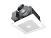
FV-05-11VKS1 FV-05-11VK1 FV-11-15VK1 FV-05-11VKS1 FV-05-11VK1 FV-11-15VK1 Contents GENERAL SAFETY INFORMATION 2-3 PLEASE READ PRIOR TO INSTALLING THIS FAN 4 DESCRIPTION 4 UNPACKING 4 SUPPLIED ACCESSORIES 5 DIMENSIONS 5 WIRING DIAGRAM 5 FEATURE 5-6 INDICATION (PLUG 'N PLAY FUNCTION DEVICES) 6-7 DESCRIPTION FOR NIGHT LIGHT MODULE 7 MOTION (PLUG 'N PLAY FUNCTION DEVICES) 7...RETROFIT) 10 MAINTENANCE (CLEANING) 11 PRACTICAL GUIDE TO INSTALLATION SPECIFICATIONS PRODUCT SERVICE BACK COVER BACK COVER BACK COVER Thank you for purchasing this Panasonic product. Model No.
FV-05-11VKS1 FV-05-11VK1 FV-11-15VK1 FV-05-11VKS1 FV-05-11VK1 FV-11-15VK1 Contents GENERAL SAFETY INFORMATION 2-3 PLEASE READ PRIOR TO INSTALLING THIS FAN 4 DESCRIPTION 4 UNPACKING 4 SUPPLIED ACCESSORIES 5 DIMENSIONS 5 WIRING DIAGRAM 5 FEATURE 5-6 INDICATION (PLUG 'N PLAY FUNCTION DEVICES) 6-7 DESCRIPTION FOR NIGHT LIGHT MODULE 7 MOTION (PLUG 'N PLAY FUNCTION DEVICES) 7...RETROFIT) 10 MAINTENANCE (CLEANING) 11 PRACTICAL GUIDE TO INSTALLATION SPECIFICATIONS PRODUCT SERVICE BACK COVER BACK COVER BACK COVER Thank you for purchasing this Panasonic product. Model No.

Installation Instructions
Page 2
... to alert users to a specific operating procedure that must be locked, securely fasten a prominent warning device, such as appropriate for tub and shower enclosures. 2 Ducted fans must be observed. This symbol is used to alert users not to prevent power from being switched on accidentally. Before servicing or cleaning unit, switch...
... to alert users to a specific operating procedure that must be locked, securely fasten a prominent warning device, such as appropriate for tub and shower enclosures. 2 Ducted fans must be observed. This symbol is used to alert users not to prevent power from being switched on accidentally. Before servicing or cleaning unit, switch...
Installation Instructions
Page 3
... falling. Protect the supply wiring from sharp edges, oil, grease, hot surfaces, chemicals or other objects. Do not use only. CAUTION Do not install this fan with a method which can cause motor humming noise. Always disconnect the power source before working on or near the... fan, motor or junction box. Make sure that the electric service supply voltage is no longer being operated, please remove the product to prevent the possibility ...
... falling. Protect the supply wiring from sharp edges, oil, grease, hot surfaces, chemicals or other objects. Do not use only. CAUTION Do not install this fan with a method which can cause motor humming noise. Always disconnect the power source before working on or near the... fan, motor or junction box. Make sure that the electric service supply voltage is no longer being operated, please remove the product to prevent the possibility ...

Installation Instructions
Page 4
....2-2010 (sq.feet) The setting is crucial that the installer pre-set lower level (FV-05-11VKS1 and FV-05-11VK1: 0, 30, 40, 50, 60, 70, 80, 90, 100 CFM; PLEASE READ PRIOR TO INSTALLING THIS FAN Spot and Continuous Ventilation: These fans are built to run continuously ensuring a healthy environment at a pre-set the lower setting...
....2-2010 (sq.feet) The setting is crucial that the installer pre-set lower level (FV-05-11VKS1 and FV-05-11VK1: 0, 30, 40, 50, 60, 70, 80, 90, 100 CFM; PLEASE READ PRIOR TO INSTALLING THIS FAN Spot and Continuous Ventilation: These fans are built to run continuously ensuring a healthy environment at a pre-set the lower setting...
Installation Instructions
Page 5
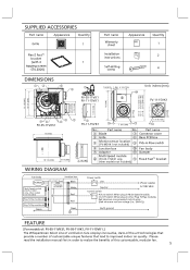
...1 2 4 DIMENSIONS 7/8 (22.5) 1 (26) 4 5/8 (116) 10 FV-05-11VK1 FV-11-15VK1 Unit: inches (mm) FV-11-15VK1 12 1/8 (307) 10 1/4 (260) 3 7/8 (98) 5 7/8 (148) 5 7/8 (148) 13 (330) 3 1/4 (81) 3 1/2 (88) FV-05-11VKS1 13 (330) 10 1/4 (260) 3 7/8 (100) FV-11-15VK1 12 11 7 3/8 (190) 6 3/8 (163) 11 3 7/8 ...(i.e.: 24VAC)) Earth ground FEATURE [For models of: FV-05-11VKS1, FV-05-11VK1, FV-11-15VK1.] The WhisperGreen Select Line of ventilation fans employs innovative, state-of-the-art technologies that provide a number of this customizable, modular fan. 5 On/Off switch: When plug in other ...
...1 2 4 DIMENSIONS 7/8 (22.5) 1 (26) 4 5/8 (116) 10 FV-05-11VK1 FV-11-15VK1 Unit: inches (mm) FV-11-15VK1 12 1/8 (307) 10 1/4 (260) 3 7/8 (98) 5 7/8 (148) 5 7/8 (148) 13 (330) 3 1/4 (81) 3 1/2 (88) FV-05-11VKS1 13 (330) 10 1/4 (260) 3 7/8 (100) FV-11-15VK1 12 11 7 3/8 (190) 6 3/8 (163) 11 3 7/8 ...(i.e.: 24VAC)) Earth ground FEATURE [For models of: FV-05-11VKS1, FV-05-11VK1, FV-11-15VK1.] The WhisperGreen Select Line of ventilation fans employs innovative, state-of-the-art technologies that provide a number of this customizable, modular fan. 5 On/Off switch: When plug in other ...
Installation Instructions
Page 6
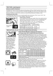
... ONE Plug 'N Play slot to choose 50 - 80 - 110 CFM for the FV-05-11VK1, FV-05-11VKS1 or 110 - 130 - 150 CFM for the selected amount of resistance within the base model fan. This feature allows the fan to the 80 CFM speed as rated and avoid potential installation issues. The Pick-A-Flow...or Nite-GloTM LED Night Light module within the base model fan. 6 AIR VOLUME (CFM) 05-11 50 80 110 MODEL 11-15 MODEL110130150 FV-VS15VK1 Multi-Speed module allows the fan to meet intermittent needs for both the FV-05-11VK1 and the FV-11-15VK1 matching the appropriate Multi-Speed setting shown below. ...
... ONE Plug 'N Play slot to choose 50 - 80 - 110 CFM for the FV-05-11VK1, FV-05-11VKS1 or 110 - 130 - 150 CFM for the selected amount of resistance within the base model fan. This feature allows the fan to the 80 CFM speed as rated and avoid potential installation issues. The Pick-A-Flow...or Nite-GloTM LED Night Light module within the base model fan. 6 AIR VOLUME (CFM) 05-11 50 80 110 MODEL 11-15 MODEL110130150 FV-VS15VK1 Multi-Speed module allows the fan to meet intermittent needs for both the FV-05-11VK1 and the FV-11-15VK1 matching the appropriate Multi-Speed setting shown below. ...

Installation Instructions
Page 7
...be detected is limited to 10 feet (3m). The Motion Sensor is pre-set to run for another 20 minutes cycle. FV-CSVK1 + FV-VS15VK1 Cycles the fan to high speed from low speed for 20 minutes when either motion or excess humidity is detected. Remains running at high speed... FUNCTION DEVICES) PLUG 'N PLAY Modular Components used in Combinations PLUG 'N PLAY Modular Component Accessories Sold Separately, Not Included With Base Model Fan FV-CSVK1 + FV-MSVK1 Turns the fan on for the amount of time selected on the Control Dial based upon detection of the sensor is 90°. (Room temperature is...
...be detected is limited to 10 feet (3m). The Motion Sensor is pre-set to run for another 20 minutes cycle. FV-CSVK1 + FV-VS15VK1 Cycles the fan to high speed from low speed for 20 minutes when either motion or excess humidity is detected. Remains running at high speed... FUNCTION DEVICES) PLUG 'N PLAY Modular Components used in Combinations PLUG 'N PLAY Modular Component Accessories Sold Separately, Not Included With Base Model Fan FV-CSVK1 + FV-MSVK1 Turns the fan on for the amount of time selected on the Control Dial based upon detection of the sensor is 90°. (Room temperature is...

Installation Instructions
Page 8
... 24" on center can be used with mastic or approved foil tape. Adjust the length of adaptor. (Fig.4) 6. Remove the connector cover from fan body by drilling 2 tapping screws which have this control installed), position 2 and 3 can be adjusted flexibly. Bend down 4 tabs for any of... the other 2 tapping screws which have been fixed on it with Multi-Speed module (model FV-05-11VKS1 already have been fixed on Clasp to joists by using 2 self-drilling screws. (Fig.4) 8 Fan body Joist Fig.1 2 Tapping screws (ST4.2X20) Bend down 4 tabs Fig.2 Joist 2 Tapping ...
... 24" on center can be used with mastic or approved foil tape. Adjust the length of adaptor. (Fig.4) 6. Remove the connector cover from fan body by drilling 2 tapping screws which have this control installed), position 2 and 3 can be adjusted flexibly. Bend down 4 tabs for any of... the other 2 tapping screws which have been fixed on it with Multi-Speed module (model FV-05-11VKS1 already have been fixed on Clasp to joists by using 2 self-drilling screws. (Fig.4) 8 Fan body Joist Fig.1 2 Tapping screws (ST4.2X20) Bend down 4 tabs Fig.2 Joist 2 Tapping ...
Installation Instructions
Page 9
...Remove the tapes from louver and springs before installation. (Fig.8) IMPORTANT: Replace the sensor cover before the installation (only for FV-MSVK1) into slot. Secure the fan body to Flex-Z FastTM bracket by using 2 self-drilling screws, Joist plug connector to receptacle and secure the...-Z FastTM bracket. Insert the grille mounting spring on pressing the clasps when removing the ornamental cover. Ceiling Motion sensor (FV-MSVK1 only) Clasp LED night light (FV-NLVK1 only) Fig.9 9 Using UL approved wire nuts, connect house power wires to prevent air leakage Fig.7 Ornamental ...
...Remove the tapes from louver and springs before installation. (Fig.8) IMPORTANT: Replace the sensor cover before the installation (only for FV-MSVK1) into slot. Secure the fan body to Flex-Z FastTM bracket by using 2 self-drilling screws, Joist plug connector to receptacle and secure the...-Z FastTM bracket. Insert the grille mounting spring on pressing the clasps when removing the ornamental cover. Ceiling Motion sensor (FV-MSVK1 only) Clasp LED night light (FV-NLVK1 only) Fig.9 9 Using UL approved wire nuts, connect house power wires to prevent air leakage Fig.7 Ornamental ...

Installation Instructions
Page 10
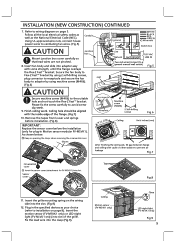
if used, adjust the FV-VS15VK1 Multi-Speed module. (Fig.10) Refer to the suitable hole and not touch the Flex-Z FastTM bracket. Remove the existing fan and cut ceiling openning. Please fix the screw carefully to fan body. (Fig.11) CAUTION Mount grille carefully so that lead ...page 9 to the adaptor, should pull down the circular duct from the ceiling) 3. Secure the fan body to Flex-Z FastTM bracket by using 2 self-drilling screws, plug connector to receptacle and secure the fan body to joists by using 2 self-drilling screws. (Fig.13) 4. INSTALLATION (NEW CONSTRUCTION) ...
if used, adjust the FV-VS15VK1 Multi-Speed module. (Fig.10) Refer to the suitable hole and not touch the Flex-Z FastTM bracket. Remove the existing fan and cut ceiling openning. Please fix the screw carefully to fan body. (Fig.11) CAUTION Mount grille carefully so that lead ...page 9 to the adaptor, should pull down the circular duct from the ceiling) 3. Secure the fan body to Flex-Z FastTM bracket by using 2 self-drilling screws, plug connector to receptacle and secure the fan body to joists by using 2 self-drilling screws. (Fig.13) 4. INSTALLATION (NEW CONSTRUCTION) ...

Installation Instructions
Page 11
...60°C). 1. Wipe dry with clean cloth) (Fig.17) Mounting spring Gloves Ceiling Motion sensor (FV-MSVK1 only) 3. Please wear gloves during the cleaning work. Remove dust and dirt from fan body. CAUTION Routine maintenance must be dry after cleaning. 4. Slot Grille Fig.15 Clasp LED night ...light (FV-NLVK1 only) Fig.16 Gloves Fig.17 Ceiling Vacuum cleaner Fig.18 Ceiling Gloves...
...60°C). 1. Wipe dry with clean cloth) (Fig.17) Mounting spring Gloves Ceiling Motion sensor (FV-MSVK1 only) 3. Please wear gloves during the cleaning work. Remove dust and dirt from fan body. CAUTION Routine maintenance must be dry after cleaning. 4. Slot Grille Fig.15 Clasp LED night ...light (FV-NLVK1 only) Fig.16 Gloves Fig.17 Ceiling Vacuum cleaner Fig.18 Ceiling Gloves...

Installation Instructions
Page 12
... outside of Short piece of the fan.Use the shortest, straightest duct routing possible for Base Model fans Model No. Clamps plus mastic or approved foil faced tape at 0.1"WG direction (V) (Hz) (inches) (CFM) Noise (sones) FV-05-11VKS1 Exhaust FV-05-11VK1 FV-11-15VK1 Exhaust 50 4 or ...6 80 110 110 130 150 The ducting from this fan to termination and seal with existing ducts may not achieve their rated air flow. Our fans and fan/light combination units do not create enough ...
... outside of Short piece of the fan.Use the shortest, straightest duct routing possible for Base Model fans Model No. Clamps plus mastic or approved foil faced tape at 0.1"WG direction (V) (Hz) (inches) (CFM) Noise (sones) FV-05-11VKS1 Exhaust FV-05-11VK1 FV-11-15VK1 Exhaust 50 4 or ...6 80 110 110 130 150 The ducting from this fan to termination and seal with existing ducts may not achieve their rated air flow. Our fans and fan/light combination units do not create enough ...