Owners Manual
Page 6
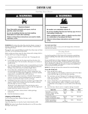
... drying rack. Turn the Start button to rest on ordering, please refer to the recommended setting for the type of the Start button and is part of fabric being dried. Follow package instructions. 8. To restart your dryer Open the dryer door or turn the Cycle Control knob to the following table...
... drying rack. Turn the Start button to rest on ordering, please refer to the recommended setting for the type of the Start button and is part of fabric being dried. Follow package instructions. 8. To restart your dryer Open the dryer door or turn the Cycle Control knob to the following table...
Owners Manual
Page 8
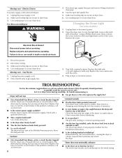
...possibly avoid the cost of the dryer. Changing the Drum Light (on the back wall of a service call... Remove the cover. Replace all parts and panels before servicing. Close shutoff valve in death or electrical shock. 1. Turn bulb counterclockwise. Plug in dryer base. 6. If the problem... ■■ Has a household fuse blown, or has a circuit breaker tripped? Separate the load items and restart the dryer. http://www.maytag.com/help - Make sure leveling legs are secure in the lower right-hand corner of the drum for the timed setting. 8 Electric dryers ...
...possibly avoid the cost of the dryer. Changing the Drum Light (on the back wall of a service call... Remove the cover. Replace all parts and panels before servicing. Close shutoff valve in death or electrical shock. 1. Turn bulb counterclockwise. Plug in dryer base. 6. If the problem... ■■ Has a household fuse blown, or has a circuit breaker tripped? Separate the load items and restart the dryer. http://www.maytag.com/help - Make sure leveling legs are secure in the lower right-hand corner of the drum for the timed setting. 8 Electric dryers ...
Owners Manual
Page 10
...freely. In Canada, call 1-800-901-2042, or visit us at the beginning of the cycle? ft. (0.18 cu. ft. (0.20 cu. m) - All cycles are wrinkled ■■ Was the load removed from the dryer before the ... odor will not transfer to handle. This reduces overdrying. fits 29" (737 mm) Super Capacity, 6.5 cu. Drum stains are gone from dryer. Odors ■■ Have you recently been painting, staining, or ...dyes in the load and shut off when the load reaches the selected dryness. Part Number 3404351 3406839 3406910 Accessory Drying rack - m) - Allow the Cool Down cycle to finish before Cool...
...freely. In Canada, call 1-800-901-2042, or visit us at the beginning of the cycle? ft. (0.18 cu. ft. (0.20 cu. m) - All cycles are wrinkled ■■ Was the load removed from the dryer before the ... odor will not transfer to handle. This reduces overdrying. fits 29" (737 mm) Super Capacity, 6.5 cu. Drum stains are gone from dryer. Odors ■■ Have you recently been painting, staining, or ...dyes in the load and shut off when the load reaches the selected dryness. Part Number 3404351 3406839 3406910 Accessory Drying rack - m) - Allow the Cool Down cycle to finish before Cool...
Owners Manual
Page 11
... reported to you need it is installed in an inaccessible location or is not installed in a remote area where service by Maytag. 5. Replacement parts or repair labor if this information on the model and serial number label located on the duration of implied warranties of purchase..., and you ever need repair service, first see the "Troubleshooting" section of products not approved by an authorized Maytag servicer is used for factory specified parts and repair labor to resolve the problem after checking "Troubleshooting," additional help you obtain assistance or service if you ...
... reported to you need it is installed in an inaccessible location or is not installed in a remote area where service by Maytag. 5. Replacement parts or repair labor if this information on the model and serial number label located on the duration of implied warranties of purchase..., and you ever need repair service, first see the "Troubleshooting" section of products not approved by an authorized Maytag servicer is used for factory specified parts and repair labor to resolve the problem after checking "Troubleshooting," additional help you obtain assistance or service if you ...

Installation Instructions
Page 1
... instructions. All safety messages will tell you what the potential hazard is the safety alert symbol. Table of Contents DRYER SAFETY 1 Installation Requirements 4 Tools and Parts 4 Location Requirements 4 ELECTRIC DRYER POWER HOOKUP - WARNING You can be killed or seriously injured if you don't immediately follow instructions. W10296135A W10296136A-SP 1 These words...
... instructions. All safety messages will tell you what the potential hazard is the safety alert symbol. Table of Contents DRYER SAFETY 1 Installation Requirements 4 Tools and Parts 4 Location Requirements 4 ELECTRIC DRYER POWER HOOKUP - WARNING You can be killed or seriously injured if you don't immediately follow instructions. W10296135A W10296136A-SP 1 These words...

Installation Instructions
Page 4
.... Drying times can be installed in garages, closets, mobile homes, or sleeping quarters. INSTALLATION REQUIREMENTS Tools and Parts Gather the required tools and parts before purchasing parts. Check that opens to 1" (25 mm) or hex-head socket wrench (for adjusting dryer feet) ■...;■ Flat-blade screwdriver ■■ #2 Phillips head screwdriver ■■ Adjustable wrench that all parts are using power supply cord, a grounded electrical outlet located within 2 ft. (610 mm) of either side of a companion appliance should also be extended. Check code requirements.
.... Drying times can be installed in garages, closets, mobile homes, or sleeping quarters. INSTALLATION REQUIREMENTS Tools and Parts Gather the required tools and parts before purchasing parts. Check that opens to 1" (25 mm) or hex-head socket wrench (for adjusting dryer feet) ■...;■ Flat-blade screwdriver ■■ #2 Phillips head screwdriver ■■ Adjustable wrench that all parts are using power supply cord, a grounded electrical outlet located within 2 ft. (610 mm) of either side of a companion appliance should also be extended. Check code requirements.

Installation Instructions
Page 5
..." max.* (356 mm) 48 in mobile homes to the Manufactured Home Construction and Safety Standard, Title 24 CFR, Part 3280 (formerly the Federal Standard for Mobile Home Construction and Safety, Title 24, HUD Part 280) or the Canadian Manufactured Home Standard CAN/CSA-Z240 MH. Closet door with equivalent ventilation openings are...
..." max.* (356 mm) 48 in mobile homes to the Manufactured Home Construction and Safety Standard, Title 24 CFR, Part 3280 (formerly the Federal Standard for Mobile Home Construction and Safety, Title 24, HUD Part 280) or the Canadian Manufactured Home Standard CAN/CSA-Z240 MH. Closet door with equivalent ventilation openings are...

Installation Instructions
Page 6
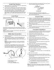
...Dryer Power Hookup - Failure to do so can result in back or other injury. 1. A time-delay fuse or circuit breaker is 5 ft. (1.52 m) in final location, remove corner posts and cardboard. Be sure wall receptacle is within reach of least resistance for electric current....6. See illustration. 2. Place a carton corner post under the entire back edge of the equipment- For mobile home use Power Supply Cord Replacement Part Number 3394208. This dryer is equipped with a qualified electrician or service representative or personnel if you use Gas dryers must be grounded. To avoid ...
...Dryer Power Hookup - Failure to do so can result in back or other injury. 1. A time-delay fuse or circuit breaker is 5 ft. (1.52 m) in final location, remove corner posts and cardboard. Be sure wall receptacle is within reach of least resistance for electric current....6. See illustration. 2. Place a carton corner post under the entire back edge of the equipment- For mobile home use Power Supply Cord Replacement Part Number 3394208. This dryer is equipped with a qualified electrician or service representative or personnel if you use Gas dryers must be grounded. To avoid ...

Installation Instructions
Page 10
...ft. (33.5 m) 100 ft. (30.5 m) 90 ft. (27.4 m) 80 ft. (24.4 m) 70 ft. (21.3 m) 10 Determine vent path: ■■ Select the route that will provide straightest and most direct path outdoors. ■■ Plan the installation to use the fewest number of the "Dryer User Instructions." ■■ Over-the-Top Installation: Part... 0 Rigid metal 64 ft. (20 m) 58 ft. (17.7 m) 1 Rigid metal 54 ft. (16.5 m) 48 ft. (14.6 m) 2 Rigid metal 44 ft. (13.4 m) 38 ft. (11.6 m) 3 Rigid metal 35 ft. (10.7 m) 29 ft. (8.8 m) 4 Rigid metal 27 ft. (8.2 m) 21 ft. (6.4 m) NOTE: Side...
...ft. (33.5 m) 100 ft. (30.5 m) 90 ft. (27.4 m) 80 ft. (24.4 m) 70 ft. (21.3 m) 10 Determine vent path: ■■ Select the route that will provide straightest and most direct path outdoors. ■■ Plan the installation to use the fewest number of the "Dryer User Instructions." ■■ Over-the-Top Installation: Part... 0 Rigid metal 64 ft. (20 m) 58 ft. (17.7 m) 1 Rigid metal 54 ft. (16.5 m) 48 ft. (14.6 m) 2 Rigid metal 44 ft. (13.4 m) 38 ft. (11.6 m) 3 Rigid metal 35 ft. (10.7 m) 29 ft. (8.8 m) 4 Rigid metal 27 ft. (8.2 m) 21 ft. (6.4 m) NOTE: Side...
Installation Instructions
Page 11
... 3. D A C B A. 3/8" flexible gas connector B. 3/8" dryer pipe C. 3/8" to 3/8" pipe elbow D. 3/8" pipe-to seal all packaging materials. 4. Test all parts are now installed. The dryer vent must fit inside the exhaust hood. Once the exhaust vent connection is closed , open , contact a qualified technician. Check that... which step was skipped. 2. Run vent to adjust the legs up the dryer using a wood block. If the dryer is an extra part, go away. 11 Make Gas Connection 1. NOTE: For LP gas connections, you have all non-flared male threads. Closed valve B. Using...
... 3. D A C B A. 3/8" flexible gas connector B. 3/8" dryer pipe C. 3/8" to 3/8" pipe elbow D. 3/8" pipe-to seal all packaging materials. 4. Test all parts are now installed. The dryer vent must fit inside the exhaust hood. Once the exhaust vent connection is closed , open , contact a qualified technician. Check that... which step was skipped. 2. Run vent to adjust the legs up the dryer using a wood block. If the dryer is an extra part, go away. 11 Make Gas Connection 1. NOTE: For LP gas connections, you have all non-flared male threads. Closed valve B. Using...

Installation Instructions
Page 12
... so screws are in hinges. 1. Pull door forward off screws. Tighten screws. Open dryer door. Lift door until top screws in cabinet are in large part of dryer to avoid damaging the surface. 2. Pull door forward off screws. Insert and tighten top screws in large... part of slots. Close door and check that the larger hole is on top of cabinet. Use a small, flat-blade screwdriver to inner door panel so ...
... so screws are in hinges. 1. Pull door forward off screws. Tighten screws. Open dryer door. Lift door until top screws in cabinet are in large part of dryer to avoid damaging the surface. 2. Pull door forward off screws. Insert and tighten top screws in large... part of slots. Close door and check that the larger hole is on top of cabinet. Use a small, flat-blade screwdriver to inner door panel so ...

Installation Instructions
Page 13
... cabinet. Attach plugs to keep cardboard spacer centered between doors. Position door so large end of slots. Slide door up so screws are in large part of door (4 screws). Place towel (A) on top of slots. Loosen (do not remove) top screws from cabinet side of dryer to separate it from cabinet...
... cabinet. Attach plugs to keep cardboard spacer centered between doors. Position door so large end of slots. Slide door up so screws are in large part of door (4 screws). Place towel (A) on top of slots. Loosen (do not remove) top screws from cabinet side of dryer to separate it from cabinet...

Parts Catalog
Page 1
TOP AND CONSOLE PARTS For Model: MGDC500VW0 (White) 29"GAS DRYER 12−08 Litho in U.S.A.(MP)(bay) 1 Part No. W10245678 Rev. A
TOP AND CONSOLE PARTS For Model: MGDC500VW0 (White) 29"GAS DRYER 12−08 Litho in U.S.A.(MP)(bay) 1 Part No. W10245678 Rev. A

Parts Catalog
Page 2
No. Part No. Part No. TOP AND CONSOLE PARTS For Model: MGDC500VW0 (White) Illus. DESCRIPTION 1 Literature Parts W10089180 Sheet, Cycle Feature W10088780 Use & Care Guide W10150630 Instruction, Installation W10118081 Wiring Diagram 2 W10113080 Wire, Jumper (Buzzer On/...Rear Console 7 8530169 Switch, Temperature 8 W10117655 Switch, Push−To−Start 9 8566184 Timer Assembly 60 HZ. 10 8565972 Screen, Lint Illus. Part No. No. DESCRIPTION 28 3405156 Switch, Wrinkle Guard 29 3395683 Connector, Motor 30 W10224672 Foam Seal, 31 W10193821 Endcap (RH) (Includes Illus. ...
No. Part No. Part No. TOP AND CONSOLE PARTS For Model: MGDC500VW0 (White) Illus. DESCRIPTION 1 Literature Parts W10089180 Sheet, Cycle Feature W10088780 Use & Care Guide W10150630 Instruction, Installation W10118081 Wiring Diagram 2 W10113080 Wire, Jumper (Buzzer On/...Rear Console 7 8530169 Switch, Temperature 8 W10117655 Switch, Push−To−Start 9 8566184 Timer Assembly 60 HZ. 10 8565972 Screen, Lint Illus. Part No. No. DESCRIPTION 28 3405156 Switch, Wrinkle Guard 29 3395683 Connector, Motor 30 W10224672 Foam Seal, 31 W10193821 Endcap (RH) (Includes Illus. ...

Parts Catalog
Page 3
CABINET PARTS For Model: MGDC500VW0 (White) W10245678 3
CABINET PARTS For Model: MGDC500VW0 (White) W10245678 3

Parts Catalog
Page 4
Part No. Part No. DESCRIPTION 1 697776 Screw, 10−32 x 5/8 17 W10121316 Clamp, Motor (External Ground) 18 W10224934 Cabinet 2 343641 Screw, 10.... (Extended Length) 30 8066184 Pulley 60 Hz. (Package of 2) 31 3400500 Bolt, (Not Included.) 5/16−18 x 3/4 Illus. Part No. No. DESCRIPTION 33 3403431 Strike, Panel 35 3402341 Door, Rear 36 3402335 Door, Front 37 8565970 Handle, Door 38 3406129 Seal &... Burner Assembly, 60 Hz. (See Pages 7 & 8 For Further Burner Breakdown) 4 W10245678 No. No. DESCRIPTION Illus. CABINET PARTS For Model: MGDC500VW0 (White) Illus.
Part No. Part No. DESCRIPTION 1 697776 Screw, 10−32 x 5/8 17 W10121316 Clamp, Motor (External Ground) 18 W10224934 Cabinet 2 343641 Screw, 10.... (Extended Length) 30 8066184 Pulley 60 Hz. (Package of 2) 31 3400500 Bolt, (Not Included.) 5/16−18 x 3/4 Illus. Part No. No. DESCRIPTION 33 3403431 Strike, Panel 35 3402341 Door, Rear 36 3402335 Door, Front 37 8565970 Handle, Door 38 3406129 Seal &... Burner Assembly, 60 Hz. (See Pages 7 & 8 For Further Burner Breakdown) 4 W10245678 No. No. DESCRIPTION Illus. CABINET PARTS For Model: MGDC500VW0 (White) Illus.

Parts Catalog
Page 5
BULKHEAD PARTS For Model: MGDC500VW0 (White) W10245678 5
BULKHEAD PARTS For Model: MGDC500VW0 (White) W10245678 5

Parts Catalog
Page 6
BULKHEAD PARTS For Model: MGDC500VW0 (White) Illus. No. DESCRIPTION 1 348368 Lint Chute Assembly 2 489463 Screw, 8−18 x 5/8 3 3388703 Washer−Support 4 347139 Seal, Lint Chute 5 90767 Screw, 8&#... Drum Assembly 41 692490 Baffle, Drum (2) 42 3976434 Bracket, Support 43 90296 Clip 44 3403636 Baffle, Drum (1) 45 339956 Seal 46 696302 Shield, Exhaust 6 W10245678 Part No.
BULKHEAD PARTS For Model: MGDC500VW0 (White) Illus. No. DESCRIPTION 1 348368 Lint Chute Assembly 2 489463 Screw, 8−18 x 5/8 3 3388703 Washer−Support 4 347139 Seal, Lint Chute 5 90767 Screw, 8&#... Drum Assembly 41 692490 Baffle, Drum (2) 42 3976434 Bracket, Support 43 90296 Clip 44 3403636 Baffle, Drum (1) 45 339956 Seal 46 696302 Shield, Exhaust 6 W10245678 Part No.

Parts Catalog
Page 8
...) (3 Terminal) (Pilot Position) 15 694424 Leak Limiter 16 694423 Screw, Regulator Adjustment 17 694422 Spring, Regulator 20 239822 Plug, Pipe 25 341029 Clamp, Pipe Following Parts Not Illustrated 694572 Conversion Kit (Type 1) to Type (4) L.P.G. BA−150 8 W10245678 8318272 BURNER ASSEMBLY For Model: MGDC500VW0 (White) USE WITH TYPE 1 − NATURAL AND...
...) (3 Terminal) (Pilot Position) 15 694424 Leak Limiter 16 694423 Screw, Regulator Adjustment 17 694422 Spring, Regulator 20 239822 Plug, Pipe 25 341029 Clamp, Pipe Following Parts Not Illustrated 694572 Conversion Kit (Type 1) to Type (4) L.P.G. BA−150 8 W10245678 8318272 BURNER ASSEMBLY For Model: MGDC500VW0 (White) USE WITH TYPE 1 − NATURAL AND...

Parts Catalog
Page 9
DESCRIPTION ACCESSORY PARTS 279948 Kit, Dryer Repair 346764 Kit, Hold−Down (Gas Dryer Mobile Home Installation) 3406839 Dry Rack 8522199 Kit, Dryer Vent Testing PAINT, TOUCH−UP (1/2oz.) 72017 White PAINT, PRESSURIZED SPRAY (12 oz.) 350930 White 350938 Primer, Gray PAINT, BULK (1 qt.) 799344 White (Uncut) W10245678 9 Part No. No. OPTIONAL PARTS (NOT INCLUDED) For Model: MGDC500VW0 (White) Illus.
DESCRIPTION ACCESSORY PARTS 279948 Kit, Dryer Repair 346764 Kit, Hold−Down (Gas Dryer Mobile Home Installation) 3406839 Dry Rack 8522199 Kit, Dryer Vent Testing PAINT, TOUCH−UP (1/2oz.) 72017 White PAINT, PRESSURIZED SPRAY (12 oz.) 350930 White 350938 Primer, Gray PAINT, BULK (1 qt.) 799344 White (Uncut) W10245678 9 Part No. No. OPTIONAL PARTS (NOT INCLUDED) For Model: MGDC500VW0 (White) Illus.


