Owners Manual
Page 1
.... 8111P524-60 © 2006 Maytag Appliances Sales Co. Form No. Printed in U.S.A. Table of our cooking products, it may be necessary to make changes to the appliance without revising this appliance. Important Safety Instructions . .1-3 Surface Cooking 4-5 Model Number Serial Number Date of purchase. U ' G SER S PRECAUCIÓN UIDE Gas Cooktop Installer: Please leave this manual...
.... 8111P524-60 © 2006 Maytag Appliances Sales Co. Form No. Printed in U.S.A. Table of our cooking products, it may be necessary to make changes to the appliance without revising this appliance. Important Safety Instructions . .1-3 Surface Cooking 4-5 Model Number Serial Number Date of purchase. U ' G SER S PRECAUCIÓN UIDE Gas Cooktop Installer: Please leave this manual...
Owners Manual
Page 6
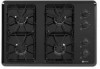
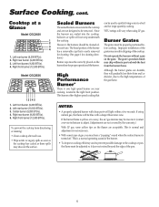
...(9,200 BTUs). 5. Since the burners are not covered by the warranty.) With LP gas, some types of gas, you may chip without a pan on your cooktop, located in chipping of the gas flame. Although the burner grates are durable, they will be adjusted so it does not... a "popping" sound when the surface burner is one high speed burner on the grate. Surface Cooking, cont. Cooktop at a Glance Model CGC2430 1 2 3 4 1. Left rear burner (9,200 BTUs). 2. Left front burner (9,200 BTUs). 4. Model CGC2536 1 2 3 4 5 1. Left front burner (9,200 BTUs). 2. Right front burner (12,500 BTUs)....
...(9,200 BTUs). 5. Since the burners are not covered by the warranty.) With LP gas, some types of gas, you may chip without a pan on your cooktop, located in chipping of the gas flame. Although the burner grates are durable, they will be adjusted so it does not... a "popping" sound when the surface burner is one high speed burner on the grate. Surface Cooking, cont. Cooktop at a Glance Model CGC2430 1 2 3 4 1. Left rear burner (9,200 BTUs). 2. Left front burner (9,200 BTUs). 4. Model CGC2536 1 2 3 4 5 1. Left front burner (9,200 BTUs). 2. Right front burner (12,500 BTUs)....
Owners Manual
Page 7
...cleaners, abrasive or caustic cleaning agents on each burner to be adjusted. STAINLESS STEEL (SELECT MODELS) • DO NOT USE ANY CLEANING PRODUCT CONTAINING CHLORINE BLEACH. • ALWAYS WIPE ...• Turn on exterior finish of cooktop. This is correctly replaced. Remove burner cap and wash in dishwasher or self-cleaning oven. Sealed Gas Burner • Clean frequently. Scrub ... nonabrasive pad. • Be careful not to be sure a pan is correctly rated for 30 minutes. Contact an authorized servicer. CONTROL KNOBS CAUTION • Remove knobs in dishwasher or self...
...cleaners, abrasive or caustic cleaning agents on each burner to be adjusted. STAINLESS STEEL (SELECT MODELS) • DO NOT USE ANY CLEANING PRODUCT CONTAINING CHLORINE BLEACH. • ALWAYS WIPE ...• Turn on exterior finish of cooktop. This is correctly replaced. Remove burner cap and wash in dishwasher or self-cleaning oven. Sealed Gas Burner • Clean frequently. Scrub ... nonabrasive pad. • Be careful not to be sure a pan is correctly rated for 30 minutes. Contact an authorized servicer. CONTROL KNOBS CAUTION • Remove knobs in dishwasher or self...
Owners Manual
Page 8
... States or Canada and applies only when the major appliance is used in the country in materials or workmanship and is reported to Maytag within 30 days from the date of purchase. 6. Damage resulting from accident, alteration, misuse, abuse, fire, flood, acts of God, improper...removal and reinstallation of your major appliance if it is used for product service if your authorized Maytag dealer to refrigerator or freezer product failures. 7. Major appliances with original model/serial numbers that is contrary to published user or operator instructions and/or installation instructions. 4. ...
... States or Canada and applies only when the major appliance is used in the country in materials or workmanship and is reported to Maytag within 30 days from the date of purchase. 6. Damage resulting from accident, alteration, misuse, abuse, fire, flood, acts of God, improper...removal and reinstallation of your major appliance if it is used for product service if your authorized Maytag dealer to refrigerator or freezer product failures. 7. Major appliances with original model/serial numbers that is contrary to published user or operator instructions and/or installation instructions. 4. ...
Installation Instructions
Page 1
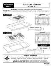
... serial plate on underside of burner box for this appliance for future reference. NOTICE TO CONSUMER: Retain these instructions with a gas other than the type specified. 30″ MODEL DIMENSIONS inches cm A 28 1/2 + 1/16 72.4 + 0.2 B 19 15/16 + 1/16 50.6 + 0.2 C 2 1/8 + 1/16 5.4 + 0.2 D 5 1/4 + 1/16 13.3 + 0.2 E 29 1/2 + 1/16 74.9 + 0.2 F 21 + 1/16 53.3 + 0.2 G 3 13/16 + 1/..., SERVICE, MAINTENANCE OR USE OF RANGE CAN RESULT IN SERIOUS INJURY OR PROPERTY DAMAGE. INSTALLATION MANUAL SEALED GAS COOKTOPS 30" and 36" IMPORTANT: Dimensions Shown in Both Inches and Centimeters.
... serial plate on underside of burner box for this appliance for future reference. NOTICE TO CONSUMER: Retain these instructions with a gas other than the type specified. 30″ MODEL DIMENSIONS inches cm A 28 1/2 + 1/16 72.4 + 0.2 B 19 15/16 + 1/16 50.6 + 0.2 C 2 1/8 + 1/16 5.4 + 0.2 D 5 1/4 + 1/16 13.3 + 0.2 E 29 1/2 + 1/16 74.9 + 0.2 F 21 + 1/16 53.3 + 0.2 G 3 13/16 + 1/..., SERVICE, MAINTENANCE OR USE OF RANGE CAN RESULT IN SERIOUS INJURY OR PROPERTY DAMAGE. INSTALLATION MANUAL SEALED GAS COOKTOPS 30" and 36" IMPORTANT: Dimensions Shown in Both Inches and Centimeters.
Installation Instructions
Page 2
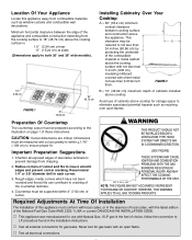
...LP gas is : 1.0″ (2.54 cm) at rear 6″ (15.24 cm) at sides (Dimensions apply to both 30″ and 36″ wide models). This clearance may be prepared according to the illustration on page 1 of these instructions. V This appliance was manufactured for use of cabinets above cooktop for... with local codes, or in each corner. 3. HOWEVER, THIS WARNING APPLIES TO ALL GAS COOKING PRODUCTS. Location Of Your Appliance Locate this appliance must be reduced to not less than 24 inches (60.96 cm) by protecting the underside of the combustible material or metal cabinet above...
...LP gas is : 1.0″ (2.54 cm) at rear 6″ (15.24 cm) at sides (Dimensions apply to both 30″ and 36″ wide models). This clearance may be prepared according to the illustration on page 1 of these instructions. V This appliance was manufactured for use of cabinets above cooktop for... with local codes, or in each corner. 3. HOWEVER, THIS WARNING APPLIES TO ALL GAS COOKING PRODUCTS. Location Of Your Appliance Locate this appliance must be reduced to not less than 24 inches (60.96 cm) by protecting the underside of the combustible material or metal cabinet above...
Installation Instructions
Page 3
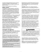
... of water column (30″ models) on pages 7 and 8 must be installed in accordance with state or other than 14″ water column. It must be installed by manufacturer. If, at a pressure of 5 inches of water column (36″ models), 4 inches of LP gas. Natural gas should use with the... factory for use with CAN/CSA -- NOTE: In Canada, gas utilization codes prohibit use with the appliance gas pressure regulator supplied with local codes. Check the cooktop serial plate to see if the cooktop is approved for Gas Burning Appliances in Mobile Homes (CSA Standard CAN/CSA -- If...
... of water column (30″ models) on pages 7 and 8 must be installed in accordance with state or other than 14″ water column. It must be installed by manufacturer. If, at a pressure of 5 inches of water column (36″ models), 4 inches of LP gas. Natural gas should use with the... factory for use with CAN/CSA -- NOTE: In Canada, gas utilization codes prohibit use with the appliance gas pressure regulator supplied with local codes. Check the cooktop serial plate to see if the cooktop is approved for Gas Burning Appliances in Mobile Homes (CSA Standard CAN/CSA -- If...
Installation Instructions
Page 6
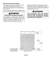
... SUPPLY AT THE WALL RECEPTACLE BEFORE SERVICING THE APPLIANCE. 3 13/16″ 9.7 cm 3 1/2″ (8.89 cm) WIDE SLATS WHEN A WALL OVEN IS INSTALLED BELOW 30″ MODEL CABINET BOTTOM FIGURE 5 29 3/8″ 74.61 cm 37 3/16″ 94.46 cm 4″ MAX. 10.16 cm User may experience occasional circuit tripping...
... SUPPLY AT THE WALL RECEPTACLE BEFORE SERVICING THE APPLIANCE. 3 13/16″ 9.7 cm 3 1/2″ (8.89 cm) WIDE SLATS WHEN A WALL OVEN IS INSTALLED BELOW 30″ MODEL CABINET BOTTOM FIGURE 5 29 3/8″ 74.61 cm 37 3/16″ 94.46 cm 4″ MAX. 10.16 cm User may experience occasional circuit tripping...
Installation Instructions
Page 9
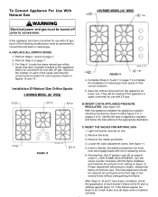
REPLACE ALL ORIFICE SPUDS. 1. Installation Of Natural Gas Orifice Spuds 5 BURNER MODEL (36″ WIDE) 1.55 1.42 1.42 1.42 1.61 FIGURE 13 4 BURNER MODEL (30″ WIDE) 1.55 1.55 1.55 1.85 FIGURE 14 4. RESET THE VALVES FOR NATURAL GAS 1. Light one burner, and set on page 7. 3. Locate the ... the LP position (see #5 on figure 12. C. Remove the rubber grommets. 4. Perform Steps 1 and 2 on page 7 to natural gas. They will produce a stable, steady blue flame of the following modifications must be turned off prior to low several times without extinguishing the flame...
REPLACE ALL ORIFICE SPUDS. 1. Installation Of Natural Gas Orifice Spuds 5 BURNER MODEL (36″ WIDE) 1.55 1.42 1.42 1.42 1.61 FIGURE 13 4 BURNER MODEL (30″ WIDE) 1.55 1.55 1.55 1.85 FIGURE 14 4. RESET THE VALVES FOR NATURAL GAS 1. Light one burner, and set on page 7. 3. Locate the ... the LP position (see #5 on figure 12. C. Remove the rubber grommets. 4. Perform Steps 1 and 2 on page 7 to natural gas. They will produce a stable, steady blue flame of the following modifications must be turned off prior to low several times without extinguishing the flame...
Installation Instructions
Page 10
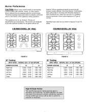
...The specified gas burner ratings typically apply to elevations up to provide optimum aeration for all gases without air shutters. Primary air adjustments are as shown in figures 15 and 16 below. 5 BURNER MODEL (36″ Wide) 4 BURNER MODEL (30″ Wide) FIGURE 15 36″ Cooktop INPUT RATES ... 1300 / 1300 1300 / 1300 FIGURE 16 30″ Cooktop INPUT RATES - If the flames have yellow tips or are designed to 2000 feet. For higher altitudes, the rates may need to be able to achieve satisfactory operation. NATURAL GAS / LP GAS (BTU/HR) BURNER LOCATION Right Front Right ...
...The specified gas burner ratings typically apply to elevations up to provide optimum aeration for all gases without air shutters. Primary air adjustments are as shown in figures 15 and 16 below. 5 BURNER MODEL (36″ Wide) 4 BURNER MODEL (30″ Wide) FIGURE 15 36″ Cooktop INPUT RATES ... 1300 / 1300 1300 / 1300 FIGURE 16 30″ Cooktop INPUT RATES - If the flames have yellow tips or are designed to 2000 feet. For higher altitudes, the rates may need to be able to achieve satisfactory operation. NATURAL GAS / LP GAS (BTU/HR) BURNER LOCATION Right Front Right ...
Installation Instructions
Page 11
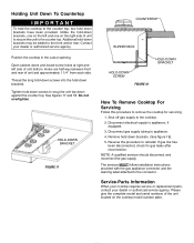
..., if equipped. 3. Disconnect electrical supply to the connector. Reverse the procedure to the cooktop. 2. NOTE: A qualified servicer should disconnect and reconnect the gas supply. Please give the complete model and serial numbers of the unit located on the left side of unit and approximately 1... 1/4″ from each side. Shut off gas supply to reinstall. Thread the long hold-down screws into the hold -down brackets may be added to appliance. 4. Remove hold -down brackets, one on the cooktop model number plate. Additional hold down brackets. Holes are...
..., if equipped. 3. Disconnect electrical supply to the connector. Reverse the procedure to the cooktop. 2. NOTE: A qualified servicer should disconnect and reconnect the gas supply. Please give the complete model and serial numbers of the unit located on the left side of unit and approximately 1... 1/4″ from each side. Shut off gas supply to reinstall. Thread the long hold-down screws into the hold -down brackets may be added to appliance. 4. Remove hold -down brackets, one on the cooktop model number plate. Additional hold down brackets. Holes are...
