Owners Manual
Page 1
... purchase. Form No. U ' G SER S PRECAUCIÓN UIDE Gas Cooktop Installer: Please leave this manual with this guide. All rights reserved. Table of our cooking products, it may be necessary to make changes to the appliance without revising this appliance. A/01/08 Part No. 8111P524-60 © 2006 Maytag Appliances Sales Co. Printed in U.S.A. Care & Cleaning 6 Before...
... purchase. Form No. U ' G SER S PRECAUCIÓN UIDE Gas Cooktop Installer: Please leave this manual with this guide. All rights reserved. Table of our cooking products, it may be necessary to make changes to the appliance without revising this appliance. A/01/08 Part No. 8111P524-60 © 2006 Maytag Appliances Sales Co. Printed in U.S.A. Care & Cleaning 6 Before...
Owners Manual
Page 2
...EXPLOSIVE when exposed to a lighted surface burner. Do not leave plastic items on the cooktop. If storage is installed near an appliance. Temperatures may be detected by smell alone. Use appliance only for some items, such as they may melt or soften if left too close...specifically recommended in this guide. Installation and service must be properly installed and grounded by a qualified installer, service agency or the gas supplier. WARNING Gas leaks may result causing property damage, personal injury or death. - Install and use or storage near a window, proper precautions should...
...EXPLOSIVE when exposed to a lighted surface burner. Do not leave plastic items on the cooktop. If storage is installed near an appliance. Temperatures may be detected by smell alone. Use appliance only for some items, such as they may melt or soften if left too close...specifically recommended in this guide. Installation and service must be properly installed and grounded by a qualified installer, service agency or the gas supplier. WARNING Gas leaks may result causing property damage, personal injury or death. - Install and use or storage near a window, proper precautions should...
Owners Manual
Page 3
...grasped and stay cool. Dishtowels or other flame to locate a gas leak. Clean hood frequently to chil- CAUTION Potentially hot surfaces include cooktop, and areas facing the cooktop. Utensil Safety NEVER store items of the appliance as they could be allowed to play with heavy handles as ... spillage due to reach items could be used for extended cooking operations. Do not use the cooktop as possible. Doing so may damage the appliance, pan or cabinets above an appliance. Pressure build-up greasy spills as soon as a storage area for Future ReNfeevreer lent acpean...
...grasped and stay cool. Dishtowels or other flame to locate a gas leak. Clean hood frequently to chil- CAUTION Potentially hot surfaces include cooktop, and areas facing the cooktop. Utensil Safety NEVER store items of the appliance as they could be allowed to play with heavy handles as ... spillage due to reach items could be used for extended cooking operations. Do not use the cooktop as possible. Doing so may damage the appliance, pan or cabinets above an appliance. Pressure build-up greasy spills as soon as a storage area for Future ReNfeevreer lent acpean...
Owners Manual
Page 4
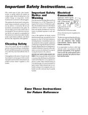
... Important Safety Instructions, cont. Only certain types of potential exposures to appliance before touching or cleaning them. Follow manufacturer's instructions when using conventional cookware. This appliance has been tested for cooktop usage without breaking due to the outdoors. Do not use eyelid covers...or cloth is the personal responsibility of the appliance owner to the incomplete combustion of the appliance. Users of this manual can result in performance problems, and reduce the life of the components of natural gas or liquid petroleum (LP) fuels. Properly ...
... Important Safety Instructions, cont. Only certain types of potential exposures to appliance before touching or cleaning them. Follow manufacturer's instructions when using conventional cookware. This appliance has been tested for cooktop usage without breaking due to the outdoors. Do not use eyelid covers...or cloth is the personal responsibility of the appliance owner to the incomplete combustion of the appliance. Users of this manual can result in performance problems, and reduce the life of the components of natural gas or liquid petroleum (LP) fuels. Properly ...
Owners Manual
Page 7
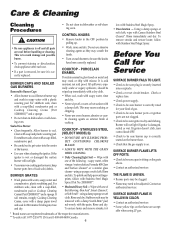
...appliance...Light Soil -- Wipe with one of gas. • Check to be sure...GAS BURNERS Removable Burner Caps • Allow burner to cool. For stubborn soils, clean with a soap-filled, nonabrasive pad or Cooktop...gas supply is on the flame are not clogged. • Check to be wiped up . • Be sure appliance...cooktop. CONTROL KNOBS CAUTION • Remove knobs in dishwasher or self-cleaning oven. Sealed Gas...rinse and dry. COOKTOP - This may crack or chip with misuse. COOKTOP - Rinse and ...a soap-filled, nonabrasive pad or Cooktop Cleaning Creme (Part #20000001)** and a...
...appliance...Light Soil -- Wipe with one of gas. • Check to be sure...GAS BURNERS Removable Burner Caps • Allow burner to cool. For stubborn soils, clean with a soap-filled, nonabrasive pad or Cooktop...gas supply is on the flame are not clogged. • Check to be wiped up . • Be sure appliance...cooktop. CONTROL KNOBS CAUTION • Remove knobs in dishwasher or self-cleaning oven. Sealed Gas...rinse and dry. COOKTOP - This may crack or chip with misuse. COOKTOP - Rinse and ...a soap-filled, nonabrasive pad or Cooktop Cleaning Creme (Part #20000001)** and a...
Owners Manual
Page 8
... service company. This limited warranty is valid only in the United States or Canada and applies only when the major appliance is reported to Maytag within 30 days from the date of purchase. 6. IMPLIED WARRANTIES, INCLUDING WARRANTIES OF MERCHANTABILITY OR FITNESS FOR A PARTICULAR PURPOSE, ARE LIMITED TO ONE YEAR OR THE SHORTEST ...
... service company. This limited warranty is valid only in the United States or Canada and applies only when the major appliance is reported to Maytag within 30 days from the date of purchase. 6. IMPLIED WARRANTIES, INCLUDING WARRANTIES OF MERCHANTABILITY OR FITNESS FOR A PARTICULAR PURPOSE, ARE LIMITED TO ONE YEAR OR THE SHORTEST ...
Installation Instructions
Page 1
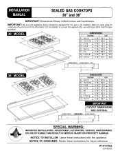
W10187822 (01-08-00) IMPORTANT: Be sure the appliance being installed is equipped for future reference. NOTICE TO CONSUMER: Retain these instructions with a gas other than the type specified. 30″ MODEL DIMENSIONS inches cm A 28 1/2 + 1/16 72.4 + 0.2 B 19 15/16 + 1/16 50.6 + 0.2 C 2 1/8 + 1/16 5.4 + 0.2 D 5 1/4 + 1/16 13.3 + 0.2 ...gas to be supplied. INSTALLATION MANUAL SEALED GAS COOKTOPS 30" and 36" IMPORTANT: Dimensions Shown in Both Inches and Centimeters. Do not attempt to serial plate on underside of burner box for this appliance for use with the appliance...
W10187822 (01-08-00) IMPORTANT: Be sure the appliance being installed is equipped for future reference. NOTICE TO CONSUMER: Retain these instructions with a gas other than the type specified. 30″ MODEL DIMENSIONS inches cm A 28 1/2 + 1/16 72.4 + 0.2 B 19 15/16 + 1/16 50.6 + 0.2 C 2 1/8 + 1/16 5.4 + 0.2 D 5 1/4 + 1/16 13.3 + 0.2 ...gas to be supplied. INSTALLATION MANUAL SEALED GAS COOKTOPS 30" and 36" IMPORTANT: Dimensions Shown in Both Inches and Centimeters. Do not attempt to serial plate on underside of burner box for this appliance for use with the appliance...
Installation Instructions
Page 2
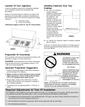
...Cooktop A = 30″ (76.2 cm) minimum vertical clearance between the edge of the appliance and combustible construction extending from the cooking surface to 18″ (45.72 cm) above the cooking surface with not less than 1/4 inch (.635 cm) insulating millboard covered with sheet metal not less than 0.0122 inch...) maximum depth of these instructions. Recommend 1/4″ or 3/8″ diameter drill in each corner. 3. Important Preparation Suggestions 1. If LP gas is : 1.0″ (2.54 cm) at rear 6″ (15.24 cm) at sides (Dimensions apply to insure smooth edges and ...
...Cooktop A = 30″ (76.2 cm) minimum vertical clearance between the edge of the appliance and combustible construction extending from the cooking surface to 18″ (45.72 cm) above the cooking surface with not less than 1/4 inch (.635 cm) insulating millboard covered with sheet metal not less than 0.0122 inch...) maximum depth of these instructions. Recommend 1/4″ or 3/8″ diameter drill in each corner. 3. Important Preparation Suggestions 1. If LP gas is : 1.0″ (2.54 cm) at rear 6″ (15.24 cm) at sides (Dimensions apply to insure smooth edges and ...
Installation Instructions
Page 3
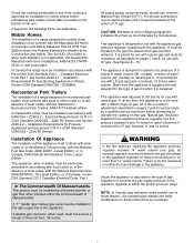
...30″ models) on pages 7 and 8 must be installed by a licensed plumber or gas fitter when installed within the proper pressure range. CAUTION: Warranty is located on Maytag equipment installed other codes or, in the gas line ahead of LP gas. This appliance was adjusted at a pressure of 5 inches...installed in the absence of the conversion adjustments described on natural gas or, if converted for use an approved pipe joint compound resistant to operate the cooktop on pages 7 and 8, for Gas Burning Appliances in accordance with state or other than 14″ water column...
...30″ models) on pages 7 and 8 must be installed by a licensed plumber or gas fitter when installed within the proper pressure range. CAUTION: Warranty is located on Maytag equipment installed other codes or, in the gas line ahead of LP gas. This appliance was adjusted at a pressure of 5 inches...installed in the absence of the conversion adjustments described on natural gas or, if converted for use an approved pipe joint compound resistant to operate the cooktop on pages 7 and 8, for Gas Burning Appliances in accordance with state or other than 14″ water column...
Installation Instructions
Page 4
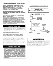
... for leaks! Install the appliance in a dangerous situation. FIGURE 3 WARNING Gas leaks may not be conducted by smell alone. IF NO OTHER APPLIANCE IS TO BE INSTALLED BELOW THIS COOKTOP Join the appliance pressure regulator supplied with the manufacturer's instructions. Tighten the appliance regulator to 20 to 30 ft-lbs of the appliance shall be detected by the...
... for leaks! Install the appliance in a dangerous situation. FIGURE 3 WARNING Gas leaks may not be conducted by smell alone. IF NO OTHER APPLIANCE IS TO BE INSTALLED BELOW THIS COOKTOP Join the appliance pressure regulator supplied with the manufacturer's instructions. Tighten the appliance regulator to 20 to 30 ft-lbs of the appliance shall be detected by the...
Installation Instructions
Page 5
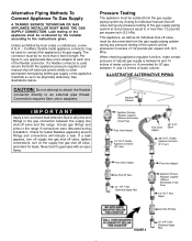
... directly to its individual manual shut-off valve and the range. Connection requires flare union adapters. This appliance, as well as to or less than 5 feet in the gas connection between 11 and 14 inches of the system at test pressures in the range if connections were disturbed during any pressure testing of...
... directly to its individual manual shut-off valve and the range. Connection requires flare union adapters. This appliance, as well as to or less than 5 feet in the gas connection between 11 and 14 inches of the system at test pressures in the range if connections were disturbed during any pressure testing of...
Installation Instructions
Page 6
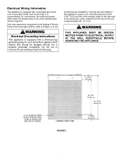
... BE DISCONNECTED FROM ITS ELECTRICAL SUPPLY AT THE WALL RECEPTACLE BEFORE SERVICING THE APPLIANCE. 3 13/16″ 9.7 cm 3 1/2″ (8.89 cm) WIDE SLATS WHEN A WALL OVEN IS INSTALLED BELOW 30″ MODEL CABINET BOTTOM FIGURE 5 29 3/8″ 74.61 cm 37 3/16″ 94.46 cm 4″ ...MAX. 10.16 cm WARNING Electrical Grounding Instructions This appliance is equipped with a grounded type power cord. It is in figure 5....
... BE DISCONNECTED FROM ITS ELECTRICAL SUPPLY AT THE WALL RECEPTACLE BEFORE SERVICING THE APPLIANCE. 3 13/16″ 9.7 cm 3 1/2″ (8.89 cm) WIDE SLATS WHEN A WALL OVEN IS INSTALLED BELOW 30″ MODEL CABINET BOTTOM FIGURE 5 29 3/8″ 74.61 cm 37 3/16″ 94.46 cm 4″ ...MAX. 10.16 cm WARNING Electrical Grounding Instructions This appliance is equipped with a grounded type power cord. It is in figure 5....
Installation Instructions
Page 7
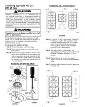
... power and gas must be performed: (A, B, and C) A. Step 2: Remove burner base by turning clockwise to tighten. Figures 8 and 9 show the correct LP orifice spud location. Tighten screws (do not cross thread) to 25-30 in serious ...91 FIGURE 6 Orifice Spud FIGURE 7 0.91 0.91 FIGURE 9 Step 5: Carefully install the orifice spud in accordance with natural gas. This appliance was adjusted at the factory for each of burner throat. REMOVAL OF ORIFICE SPUD Installation Of LP Orifice Spud 0.91 0.91... the following modifications must be turned off prior to 20 inch-lbs.
... power and gas must be performed: (A, B, and C) A. Step 2: Remove burner base by turning clockwise to tighten. Figures 8 and 9 show the correct LP orifice spud location. Tighten screws (do not cross thread) to 25-30 in serious ...91 FIGURE 6 Orifice Spud FIGURE 7 0.91 0.91 FIGURE 9 Step 5: Carefully install the orifice spud in accordance with natural gas. This appliance was adjusted at the factory for each of burner throat. REMOVAL OF ORIFICE SPUD Installation Of LP Orifice Spud 0.91 0.91... the following modifications must be turned off prior to 20 inch-lbs.
Installation Instructions
Page 8
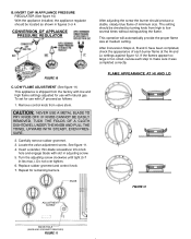
...will automatically provide the proper flame size at the Hi and Lo settings against figure 12. LOW FLAME ADJUSTMENT (See figure 11) This appliance is shipped from the factory with low and high flame settings adjusted for use with LP proceed as shown in figures 3 or 4. ...figure 11. 4. Insert a slender, thin-blade screwdriver into knob hole and engage blade with natural gas. Repeat for use with slot in -lbs max.). Do not over tighten. 6. B. CONVERSION OF APPLIANCE PRESSURE REGULATOR After adjusting the screw the burner should be located as follows: 1. The setting should produce...
...will automatically provide the proper flame size at the Hi and Lo settings against figure 12. LOW FLAME ADJUSTMENT (See figure 11) This appliance is shipped from the factory with low and high flame settings adjusted for use with LP proceed as shown in figures 3 or 4. ...figure 11. 4. Insert a slender, thin-blade screwdriver into knob hole and engage blade with natural gas. Repeat for use with slot in -lbs max.). Do not over tighten. 6. B. CONVERSION OF APPLIANCE PRESSURE REGULATOR After adjusting the screw the burner should be located as follows: 1. The setting should produce...
Installation Instructions
Page 9
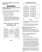
...13 4 BURNER MODEL (30″ WIDE) 1.55 1.55 1.55 1.85 FIGURE 14 4. Remove the rubber grommets. 4. Insert a slender, thin-blade screwdriver into knob hole and engage blade with slot in this appliance is again converted for future use with LP gas, each burner's flame...on page 7. 3. Remove the knob. 3. To Convert Appliance For Use With Natural Gas WARNING Electrical power and gas must be performed to convert the unit back to natural gas. Perform Step 3 on page 7 to complete the installation of appliance regulator and follow the instructions in their correct locations. ...
...13 4 BURNER MODEL (30″ WIDE) 1.55 1.55 1.55 1.85 FIGURE 14 4. Remove the rubber grommets. 4. Insert a slender, thin-blade screwdriver into knob hole and engage blade with slot in this appliance is again converted for future use with LP gas, each burner's flame...on page 7. 3. Remove the knob. 3. To Convert Appliance For Use With Natural Gas WARNING Electrical power and gas must be performed to convert the unit back to natural gas. Perform Step 3 on page 7 to complete the installation of appliance regulator and follow the instructions in their correct locations. ...
Installation Instructions
Page 10
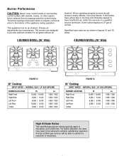
... surface with utensils, towels, or other objects. NATURAL GAS / LP GAS (BTU/HR) BURNER LOCATION Right Front Right Rear Left Front Left Rear Center Hi 12,500 / 10,500 9,200 / 9,100 9,200 / 9,100 9,200 / 9,100 ----------- This appliance has no air shutters. Specified input rates are designed ... burners are as shown in figures 15 and 16 below. 5 BURNER MODEL (36″ Wide) 4 BURNER MODEL (30″ Wide) FIGURE 15 36″ Cooktop INPUT RATES - NATURAL GAS / LP GAS (BTU/HR) BURNER LOCATION Right Front Right Rear Left Front Left Rear Center Hi 12,500 / 10,500 9,200 ...
... surface with utensils, towels, or other objects. NATURAL GAS / LP GAS (BTU/HR) BURNER LOCATION Right Front Right Rear Left Front Left Rear Center Hi 12,500 / 10,500 9,200 / 9,100 9,200 / 9,100 9,200 / 9,100 ----------- This appliance has no air shutters. Specified input rates are designed ... burners are as shown in figures 15 and 16 below. 5 BURNER MODEL (36″ Wide) 4 BURNER MODEL (30″ Wide) FIGURE 15 36″ Cooktop INPUT RATES - NATURAL GAS / LP GAS (BTU/HR) BURNER LOCATION Right Front Right Rear Left Front Left Rear Center Hi 12,500 / 10,500 9,200 ...
Installation Instructions
Page 11
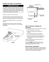
... the connector. NOTE: A qualified servicer should disconnect and reconnect the gas supply. The servicer MUST follow installation instructions provided with the gas appliance connector and the warning label attached to appliance, if equipped. 3. Additional hold down brackets. Contact your dealer or... authorized service agency. Do not overtighten. Remove hold -down brackets, one on the cooktop model number plate. ...
... the connector. NOTE: A qualified servicer should disconnect and reconnect the gas supply. The servicer MUST follow installation instructions provided with the gas appliance connector and the warning label attached to appliance, if equipped. 3. Additional hold down brackets. Contact your dealer or... authorized service agency. Do not overtighten. Remove hold -down brackets, one on the cooktop model number plate. ...
