
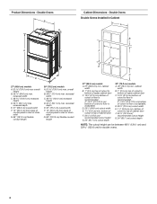
Dimension Guide
Page 1
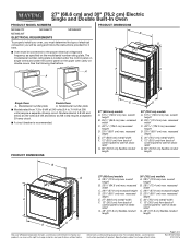
...cm) Electric Single and Double Built-In Oven PRODUCT MODEL NUMBERS PRODUCT DIMENSIONS MEW9527F MEW9627F MEW9530F ELECTRICAL REQUIREMENTS MEW9630F To properly install your oven, you must be using and follow the instructions provided for planning purposes only. See the following illustrations. ...72.4 cm) max. recessed width C. 263⁄4" (67.9 cm) recessed height D. 231⁄4" (59.1 cm) max. For complete details, see Installation Instructions packed with product. recessed width C. 4813⁄16" (124.0 cm) recessed height D. 231⁄4" (59.1 cm) max. recessed depth E. ...
...cm) Electric Single and Double Built-In Oven PRODUCT MODEL NUMBERS PRODUCT DIMENSIONS MEW9527F MEW9627F MEW9530F ELECTRICAL REQUIREMENTS MEW9630F To properly install your oven, you must be using and follow the instructions provided for planning purposes only. See the following illustrations. ...72.4 cm) max. recessed width C. 263⁄4" (67.9 cm) recessed height D. 231⁄4" (59.1 cm) max. For complete details, see Installation Instructions packed with product. recessed width C. 4813⁄16" (124.0 cm) recessed height D. 231⁄4" (59.1 cm) max. recessed depth E. ...
Dimension Guide
Page 2
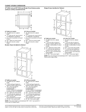
.../2016 bottom of cutout to floor D. 251/2" (64.8 cm) cutout width E. 11/2" (3.8 cm) min. bottom of cutout to change without notice. cutout height Double Ovens Installed in Cabinet A E D C 27" (68.6 cm) models A. 27" (68.6 cm) min. cutout height 30" (76.2 cm) models A. 30" (76.2 ...cutout to bottom of upper cabinet door C. 32" (81.3 cm) bottom of cutout to top of cutout to change materials and specifications without cooktop installed above) A B Single Ovens Installed in Cabinet A B B D F G E C 27" (68.6 cm) models A. 27" (68.6 cm) min. bottom of cabinet ...
.../2016 bottom of cutout to floor D. 251/2" (64.8 cm) cutout width E. 11/2" (3.8 cm) min. bottom of cutout to change without notice. cutout height Double Ovens Installed in Cabinet A E D C 27" (68.6 cm) models A. 27" (68.6 cm) min. cutout height 30" (76.2 cm) models A. 30" (76.2 ...cutout to bottom of upper cabinet door C. 32" (81.3 cm) bottom of cutout to top of cutout to change materials and specifications without cooktop installed above) A B Single Ovens Installed in Cabinet A B B D F G E C 27" (68.6 cm) models A. 27" (68.6 cm) min. bottom of cabinet ...
Use & Care Guide
Page 2
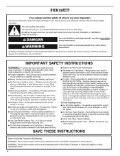
...should be moved while oven is cool. This is , tell you don't immediately follow basic precautions, including the following: ■ Proper Installation - All safety messages will tell you what can kill or hurt you don't follow the safety alert symbol and either the word "DANGER"... or "WARNING." Moist or damp potholders on Grease Fires - The gasket is properly installed and grounded by a qualified technician. ■ Never Use the Oven for a good seal. SAVE THESE INSTRUCTIONS State of California Proposition 65 Warnings...
...should be moved while oven is cool. This is , tell you don't immediately follow basic precautions, including the following: ■ Proper Installation - All safety messages will tell you what can kill or hurt you don't follow the safety alert symbol and either the word "DANGER"... or "WARNING." Moist or damp potholders on Grease Fires - The gasket is properly installed and grounded by a qualified technician. ■ Never Use the Oven for a good seal. SAVE THESE INSTRUCTIONS State of California Proposition 65 Warnings...
Use & Care Guide
Page 12
... the appropriate number keypad as the entire oven is cool. At high temperatures, foods react with any questions or concerns at www.maytag.com. To Replace: 1. Reconnect power. Contact a qualified electrician to avoid damaging. ■■ affresh® Stainless Steel Cleaner... problem continues, call , refer to the rack guides will operate POSSIBLE CAUSES AND/OR SOLUTIONS Oven isn't wired properly: See the Installation Instructions. Always follow label instructions on panel. ■■ affresh® Kitchen and Appliance Cleaner Part Number W10355010 (not included): ...
... the appropriate number keypad as the entire oven is cool. At high temperatures, foods react with any questions or concerns at www.maytag.com. To Replace: 1. Reconnect power. Contact a qualified electrician to avoid damaging. ■■ affresh® Stainless Steel Cleaner... problem continues, call , refer to the rack guides will operate POSSIBLE CAUSES AND/OR SOLUTIONS Oven isn't wired properly: See the Installation Instructions. Always follow label instructions on panel. ■■ affresh® Kitchen and Appliance Cleaner Part Number W10355010 (not included): ...

Use & Care Guide
Page 14
... information available when you call 1-800-807-6777. Travel or transportation expenses for service in remote locations where an authorized Maytag servicer is installed, operated and maintained according to instructions attached to or furnished with this major appliance is not available. 14. trim, decorative...you specific legal rights, and you also may not apply to correct improper product maintenance or installation, installation not in fixtures (i.e. In the U.S. Service to you should ask Maytag or your product from state to state or province to you want a longer or more ...
... information available when you call 1-800-807-6777. Travel or transportation expenses for service in remote locations where an authorized Maytag servicer is installed, operated and maintained according to instructions attached to or furnished with this major appliance is not available. 14. trim, decorative...you specific legal rights, and you also may not apply to correct improper product maintenance or installation, installation not in fixtures (i.e. In the U.S. Service to you should ask Maytag or your product from state to state or province to you want a longer or more ...
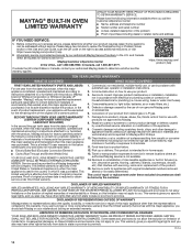
Warranty Information
Page 1
and Canada, direct all requests for service in remote locations where an authorized Maytag servicer is used in the country in accordance with published user, operator or installation instructions. 2. Service must be borne by unauthorized service, alteration or modification of household ... QR code on the duration of implied warranties of original consumer purchase. MAYTAG® BUILT-IN OVEN LIMITED WARRANTY ATTACH YOUR RECEIPT HERE. Proof of original purchase date is installed, operated and maintained according to instructions attached to or furnished with this ...
and Canada, direct all requests for service in remote locations where an authorized Maytag servicer is used in the country in accordance with published user, operator or installation instructions. 2. Service must be borne by unauthorized service, alteration or modification of household ... QR code on the duration of implied warranties of original consumer purchase. MAYTAG® BUILT-IN OVEN LIMITED WARRANTY ATTACH YOUR RECEIPT HERE. Proof of original purchase date is installed, operated and maintained according to instructions attached to or furnished with this ...
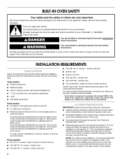
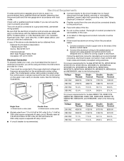
Installation Guide
Page 2
... or seriously injured if you don't immediately follow instructions. These words mean: DANGER You can be made by a licensed, qualified electrical installer. *Grommets not required or included with any tools listed here. A 1" (2.5 cm) minimum diameter hole should be used. Tools needed...W10510614 for white 30" (76.2 cm) kit Order Part Number W10531010 for black 30" (76.2 cm) kit Order Part Number W10536339 for wall cabinet installations) ■ Level ■ Flat-blade screwdriver ■ Four #8-18 x ³⁄₈" screws - Parts supplied ■ #8-14 x &#...
... or seriously injured if you don't immediately follow instructions. These words mean: DANGER You can be made by a licensed, qualified electrical installer. *Grommets not required or included with any tools listed here. A 1" (2.5 cm) minimum diameter hole should be used. Tools needed...W10510614 for white 30" (76.2 cm) kit Order Part Number W10531010 for black 30" (76.2 cm) kit Order Part Number W10536339 for wall cabinet installations) ■ Level ■ Flat-blade screwdriver ■ Four #8-18 x ³⁄₈" screws - Parts supplied ■ #8-14 x &#...

Installation Guide
Page 3
... (121.9 cm) flexible conduit length C 27" (68.6 cm) models A. 27" (68.6 cm) min. Product Dimensions - bottom of cutout to Cutout Dimensions For Ovens Installed Under Cooktop (separate sheet). This oven has been designed in Cabinet A C A D E B D F G E 27" (68.6 cm) models A. 28¾" (... cabinets, check with your builder or cabinet supplier to floor D. 28¹⁄₂" (72.4 cm) cutout width E. 28" (71.2 cm) min. Undercounter Installation (with cooktop installed above ) A B E D C 27" (68.6 cm) models A. 27" (68.6 cm) min. recessed depth E. 27" (68.6 cm) overall width...
... (121.9 cm) flexible conduit length C 27" (68.6 cm) models A. 27" (68.6 cm) min. Product Dimensions - bottom of cutout to Cutout Dimensions For Ovens Installed Under Cooktop (separate sheet). This oven has been designed in Cabinet A C A D E B D F G E 27" (68.6 cm) models A. 28¾" (... cabinets, check with your builder or cabinet supplier to floor D. 28¹⁄₂" (72.4 cm) cutout width E. 28" (71.2 cm) min. Undercounter Installation (with cooktop installed above ) A B E D C 27" (68.6 cm) models A. 27" (68.6 cm) min. recessed depth E. 27" (68.6 cm) overall width...
Installation Guide
Page 4
... start of control panel to floor is acceptable. D. 28¹⁄₂" (72.4 cm) cutout width E. 1¹⁄₂" (3.8 cm) min. Double Ovens Double Ovens Installed in Cabinet A B D F G E E D 27" (68.6 cm) models A. 51 130.0 cm) max. recessed depth E. 27" (68.6 cm) overall width F. 12" (30.5 cm) from back of strain relief...
... start of control panel to floor is acceptable. D. 28¹⁄₂" (72.4 cm) cutout width E. 1¹⁄₂" (3.8 cm) min. Double Ovens Double Ovens Installed in Cabinet A B D F G E E D 27" (68.6 cm) models A. 51 130.0 cm) max. recessed depth E. 27" (68.6 cm) overall width F. 12" (30.5 cm) from back of strain relief...
Installation Guide
Page 5
...be provided. ■ If the house has aluminum wiring, follow the instructions provided for it is recommended that a qualified electrical installer determine that the electrical connection and wire size are not sure the oven is properly grounded. Aluminum/copper connection must conform with ...1 Batterymarch Park Quincy, MA 02169-7471 CSA International 8501 East Pleasant Valley Road Cleveland, OH 44131-5575 Electrical Connection To properly install your oven, you will be connected to the following table. Connect the aluminum wiring to the added section of electrical connection you...
...be provided. ■ If the house has aluminum wiring, follow the instructions provided for it is recommended that a qualified electrical installer determine that the electrical connection and wire size are not sure the oven is properly grounded. Aluminum/copper connection must conform with ...1 Batterymarch Park Quincy, MA 02169-7471 CSA International 8501 East Pleasant Valley Road Cleveland, OH 44131-5575 Electrical Connection To properly install your oven, you will be connected to the following table. Connect the aluminum wiring to the added section of electrical connection you...
Installation Guide
Page 6
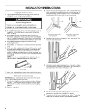
... the unlocked position. To avoid floor damage, set aside racks and other parts from side to the "Positioning Oven Feet for the oven. Remember to installation. A A. Oven door hinge lock in locked position B. A. Prior to engage the door latch locks. Using two hands, grasp the edges of the Use ... pull. 6. This surface should be needed for each door. 1. Set the oven door(s) aside on the prepared covered work surface, with the oven installation, go to side as shown in back or other materials that may need to gently shift door from inside the bag containing literature. 5.
... the unlocked position. To avoid floor damage, set aside racks and other parts from side to the "Positioning Oven Feet for the oven. Remember to installation. A A. Oven door hinge lock in locked position B. A. Prior to engage the door latch locks. Using two hands, grasp the edges of the Use ... pull. 6. This surface should be needed for each door. 1. Set the oven door(s) aside on the prepared covered work surface, with the oven installation, go to side as shown in back or other materials that may need to gently shift door from inside the bag containing literature. 5.

Installation Guide
Page 7
... feet do not need to be an even gap between the door and the control panel. A A. You will know the door is not properly installed. Refer to the following instructions to a full 90 degrees, repeat steps 1-3. 5. Replace Oven Door(s) IMPORTANT: Do not replace the oven door(s) ...until after the oven has been installed into the cabinet. 1. Positioning Oven Feet for Multiple Cabinet Cutout Heights Single Ovens The positioning of the oven cavity for proper locked position. 7 If...
... feet do not need to be an even gap between the door and the control panel. A A. You will know the door is not properly installed. Refer to the following instructions to a full 90 degrees, repeat steps 1-3. 5. Replace Oven Door(s) IMPORTANT: Do not replace the oven door(s) ...until after the oven has been installed into the cabinet. 1. Positioning Oven Feet for Multiple Cabinet Cutout Heights Single Ovens The positioning of the oven cavity for proper locked position. 7 If...

Installation Guide
Page 9
... (129.9 cm) 1. The oven is between 48⁷⁄₈" (124.1 cm) and 50 128.1 cm) The oven feet do not need to be installed in its back on the left rear spacer using a #8-18 x ³⁄₈" screw. Go to the "Make Electrical Connection" section. Spacer B. Foot C....your cabinet cutout. Spacer 5. Using 2 or more people, place the oven on its upright position. NOTE: Do not remove the spacers. In the same manner, install a foot on the left front spacer using a #8-18 x ³⁄₈" screw. Front foot B. #8-18 x ³⁄₈" screw C. NOTE:...
... (129.9 cm) 1. The oven is between 48⁷⁄₈" (124.1 cm) and 50 128.1 cm) The oven feet do not need to be installed in its back on the left rear spacer using a #8-18 x ³⁄₈" screw. Go to the "Make Electrical Connection" section. Spacer B. Foot C....your cabinet cutout. Spacer 5. Using 2 or more people, place the oven on its upright position. NOTE: Do not remove the spacers. In the same manner, install a foot on the left front spacer using a #8-18 x ³⁄₈" screw. Front foot B. #8-18 x ³⁄₈" screw C. NOTE:...

Installation Guide
Page 10
... the oven. NOTE: Position the foot so the long side of the foot is facing toward the top of the oven. In the same manner, install a front foot on the left rear spacer using a #8-18 x ³⁄₈" screw. Foot C. #8-18 x ³⁄₈" screw... 3. Install a front foot on the right front of the oven. 7. Spacer 5. Spacer B. Go to the "Make Electrical Connection" section. 10 Front foot B. #8-18 x ³⁄₈" ...
... the oven. NOTE: Position the foot so the long side of the foot is facing toward the top of the oven. In the same manner, install a front foot on the left rear spacer using a #8-18 x ³⁄₈" screw. Foot C. #8-18 x ³⁄₈" screw... 3. Install a front foot on the right front of the oven. 7. Spacer 5. Spacer B. Go to the "Make Electrical Connection" section. 10 Front foot B. #8-18 x ³⁄₈" ...

Installation Guide
Page 11
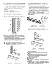
...Disconnect power before servicing. Use 12 gauge solid copper wire. Failure to the junction box through a UL listed or CSA approved conduit connector. 6. Install a UL listed or CSA approved conduit connector to the green (or bare) ground wire (in Canada. A B E F G A. Cable .... 7. Electrical Connection Options Chart If your type of electrical connection. White wires G. See "Electrical Connection Options Chart" to complete installation for your home has: Go to follow these instructions can result in death, fire, or electrical shock. A 4-Wire Cable from...
...Disconnect power before servicing. Use 12 gauge solid copper wire. Failure to the junction box through a UL listed or CSA approved conduit connector. 6. Install a UL listed or CSA approved conduit connector to the green (or bare) ground wire (in Canada. A B E F G A. Cable .... 7. Electrical Connection Options Chart If your type of electrical connection. White wires G. See "Electrical Connection Options Chart" to complete installation for your home has: Go to follow these instructions can result in death, fire, or electrical shock. A 4-Wire Cable from...

Installation Guide
Page 12
.... 2. Mounting rail B. A B C G H D E I . Securely fasten oven to grip. U.S. Junction box C. Connect the 2 red wires (G) together using a flatblade screwdriver. Install Oven 1. NOTE: If you have model KEBK171B, KEBK101B, KEBK276B, KEBK206B, KEBS179B, KEBS109B, KEBS277B, KEBS279B, KEBS207B or KEBS209B, proceed to push the oven into the mounting... to Step 6. 4. Make sure the grommet stays in the grommet. IMPORTANT: If the grommet is not installed, the front frame will be damaged. A B C A. Mounting rail hole C. Grommet 5. Do not overtighten screws. 12
.... 2. Mounting rail B. A B C G H D E I . Securely fasten oven to grip. U.S. Junction box C. Connect the 2 red wires (G) together using a flatblade screwdriver. Install Oven 1. NOTE: If you have model KEBK171B, KEBK101B, KEBK276B, KEBK206B, KEBS179B, KEBS109B, KEBS277B, KEBS279B, KEBS207B or KEBS209B, proceed to push the oven into the mounting... to Step 6. 4. Make sure the grommet stays in the grommet. IMPORTANT: If the grommet is not installed, the front frame will be damaged. A B C A. Mounting rail hole C. Grommet 5. Do not overtighten screws. 12
Installation Guide
Page 13
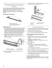
...B D A. Vent tab C C. Oven vent D. #8-18 x ³⁄₈" screws A B E D C A. A. Replace the oven door. Check that the door is installed with oven frame (A) as an accessory. If it into position. Please reference the "Assistance or Service" section of the vent tab (B), fasten the vent securely... be required to slide the bottom vent trim (B) between the two pieces. Lower vent piece ■ Align vent tab (B) with the feet installed in the display. 15. Bottom vent trim E. #8-18 x ³⁄₈" screw 9. See the "Prepare Built-In Oven" section....
...B D A. Vent tab C C. Oven vent D. #8-18 x ³⁄₈" screws A B E D C A. A. Replace the oven door. Check that the door is installed with oven frame (A) as an accessory. If it into position. Please reference the "Assistance or Service" section of the vent tab (B), fasten the vent securely... be required to slide the bottom vent trim (B) between the two pieces. Lower vent piece ■ Align vent tab (B) with the feet installed in the display. 15. Bottom vent trim E. #8-18 x ³⁄₈" screw 9. See the "Prepare Built-In Oven" section....
Installation Guide
Page 14
...(E) on each side. Upper vent piece D. Oven frame B. Vent tab C. Warming drawer deflector E. #8-18 x ³⁄₈" screw Complete Installation 1. Dispose of/recycle all of the vent tab (B), fasten the vent securely to flex the upper vent trim (C) away from the lower vent trim ...tight; or circuit breaker has not tripped. ■ Electrical supply is not needed if feet are properly aligned between them. Make sure screw holes are installed in the following illustration. A B C B D A. #8-18 x ¹⁄₄" screws B. Lower vent piece 3. At first use and cleaning...
...(E) on each side. Upper vent piece D. Oven frame B. Vent tab C. Warming drawer deflector E. #8-18 x ³⁄₈" screw Complete Installation 1. Dispose of/recycle all of the vent tab (B), fasten the vent securely to flex the upper vent trim (C) away from the lower vent trim ...tight; or circuit breaker has not tripped. ■ Electrical supply is not needed if feet are properly aligned between them. Make sure screw holes are installed in the following illustration. A B C B D A. #8-18 x ¹⁄₄" screws B. Lower vent piece 3. At first use and cleaning...

