
Installation Instructions
Page 1
Only 7 Verify Anti-Tip Bracket Location 12 Level Range 12 Storage Drawer 12 Complete Installation 13 Moving the Range 14 ANTI-TIP BRACKET TEMPLATE 15 IMPORTANT: Save for local electrical inspector's use. Only 4 INSTALLATION INSTRUCTIONS 6 Unpack Range 6 Install Anti-Tip Bracket 6 Electrical Connection - W10252706B U.S.A. U.S.A. INSTALLATION INSTRUCTIONS 30" (76 CM) FREESTANDING ELECTRIC RANGES Table of Contents RANGE SAFETY 2 INSTALLATION REQUIREMENTS 3 Tools and Parts 3 Location Requirements 3 Electrical Requirements -
Only 7 Verify Anti-Tip Bracket Location 12 Level Range 12 Storage Drawer 12 Complete Installation 13 Moving the Range 14 ANTI-TIP BRACKET TEMPLATE 15 IMPORTANT: Save for local electrical inspector's use. Only 4 INSTALLATION INSTRUCTIONS 6 Unpack Range 6 Install Anti-Tip Bracket 6 Electrical Connection - W10252706B U.S.A. U.S.A. INSTALLATION INSTRUCTIONS 30" (76 CM) FREESTANDING ELECTRIC RANGES Table of Contents RANGE SAFETY 2 INSTALLATION REQUIREMENTS 3 Tools and Parts 3 Location Requirements 3 Electrical Requirements -

Installation Instructions
Page 2
...children and adults. 2 WARNING Tip Over Hazard A child or adult can be killed or seriously injured if you don't immediately follow instructions. RANGE SAFETY Your safety and the safety of injury, and tell you what can happen if the instructions are very important. This symbol alerts you to... rear range foot. WARNING You can kill or hurt you don't follow instructions. Reconnect the anti-tip bracket, if the range is the safety alert symbol. This is moved. These words mean: DANGER You ...
...children and adults. 2 WARNING Tip Over Hazard A child or adult can be killed or seriously injured if you don't immediately follow instructions. RANGE SAFETY Your safety and the safety of injury, and tell you what can happen if the instructions are very important. This symbol alerts you to... rear range foot. WARNING You can kill or hurt you don't follow instructions. Reconnect the anti-tip bracket, if the range is the safety alert symbol. This is moved. These words mean: DANGER You ...
Installation Instructions
Page 3
...To install the antitip bracket shipped with upturned ends. ■ A UL listed strain relief. Mobile home installations require: ■ When this range must conform to be provided, the risk can be avoided. Thickness of flooring may require longer screws to anchor bracket to subfloor. Longer ...9632; ¼" nut driver and nut driver 3.2 mm) drill bit (for wood floors) 4.8 mm) carbide-tipped masonry drill bit (for concrete/ceramic floors) ■ Tin snips or large wire cutters (for Manufactured Home Installations, ANSI A225.1/NFPA 501A or local codes. Check local codes. Check ...
...To install the antitip bracket shipped with upturned ends. ■ A UL listed strain relief. Mobile home installations require: ■ When this range must conform to be provided, the risk can be avoided. Thickness of flooring may require longer screws to anchor bracket to subfloor. Longer ...9632; ¼" nut driver and nut driver 3.2 mm) drill bit (for wood floors) 4.8 mm) carbide-tipped masonry drill bit (for concrete/ceramic floors) ■ Tin snips or large wire cutters (for Manufactured Home Installations, ANSI A225.1/NFPA 501A or local codes. Check local codes. Check ...
Installation Instructions
Page 4
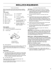
...wire gauge are adequate and in conformance with a qualified electrician or service technician if you are for dimensional clearances above the range, follow the range hood or microwave hood combination installation instructions for 25" (64.0 cm) countertop depth, 24" (61.0 cm) base .... A. 13" (33.0 cm) max. opening width E. If it is properly grounded. Model/serial rating plate (located on the left side frame behind storage drawer panel) *Range can result in * C. 36" (91.4 cm) cooktop height (max.) with zero clearance. Product Dimensions A C B A F B C D E F E D A. 27 ...
...wire gauge are adequate and in conformance with a qualified electrician or service technician if you are for dimensional clearances above the range, follow the range hood or microwave hood combination installation instructions for 25" (64.0 cm) countertop depth, 24" (61.0 cm) base .... A. 13" (33.0 cm) max. opening width E. If it is properly grounded. Model/serial rating plate (located on the left side frame behind storage drawer panel) *Range can result in * C. 36" (91.4 cm) cooktop height (max.) with zero clearance. Product Dimensions A C B A F B C D E F E D A. 27 ...
Installation Instructions
Page 5
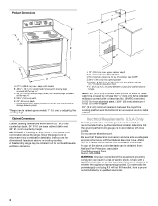
... receptacle (14-50R) The minimum conductor sized for new branch-circuit installations (1996 NEC); If local codes do not permit ground through the neutral conductor. Range Rating* 120/240 Volts 8.8 - 16.5 KW 16.6 - 22.5 KW 120/208 Volts 7.8 - 12.5 KW 12.6 - 18.5 KW Specified Rating of the "Location ...Requirements" section. ■ This range is less than the total connected load listed on the supply end. Refer to the figures in a NEMA Type 14-50P plug on the model...
... receptacle (14-50R) The minimum conductor sized for new branch-circuit installations (1996 NEC); If local codes do not permit ground through the neutral conductor. Range Rating* 120/240 Volts 8.8 - 16.5 KW 16.6 - 22.5 KW 120/208 Volts 7.8 - 12.5 KW 12.6 - 18.5 KW Specified Rating of the "Location ...Requirements" section. ■ This range is less than the total connected load listed on the supply end. Refer to the figures in a NEMA Type 14-50P plug on the model...
Installation Instructions
Page 6
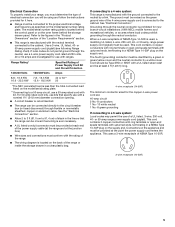
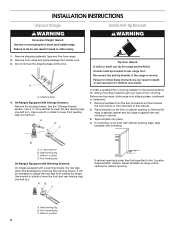
..., molding or cabinet. 3. It will be necessary to lower front leveling legs one -half turn. A. Wrench or pliers 6 Before moving range, slide range onto shipping base, cardboard or hardboard. 1. Rear leveling leg B. Shipping base 4. Contact a qualified floor covering installer for the best procedure ...in back or other injury. 1. Failure to follow these instructions can result in death or serious burns to do so can tip the range and be accessed by removing the warming drawer. Rear leveling leg C. Failure to children and adults. AB C If cabinet opening is moved...
..., molding or cabinet. 3. It will be necessary to lower front leveling legs one -half turn. A. Wrench or pliers 6 Before moving range, slide range onto shipping base, cardboard or hardboard. 1. Rear leveling leg B. Shipping base 4. Contact a qualified floor covering installer for the best procedure ...in back or other injury. 1. Failure to follow these instructions can result in death or serious burns to do so can tip the range and be accessed by removing the warming drawer. Rear leveling leg C. Failure to children and adults. AB C If cabinet opening is moved...

Installation Instructions
Page 7
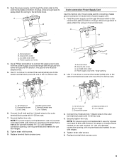
... toward you to wood floor, drill two ¹⁄₈" (3.2 mm) holes at the positions marked on the back of the range. Longer screws are available from your flooring, longer screws may be necessary to anchor the bracket to drill 2 holes at the positions marked... thickness of the terminal block. Remove plastic tag holding three 10-32 hex nuts from range. 3. Use a new 40 amp power supply cord. A B C A. Terminal block cover C. To mount anti-tip bracket to concrete or ceramic floor, use a 4.8 mm) masonry drill bit to the subfloor. U.S.A. Two mounting...
... toward you to wood floor, drill two ¹⁄₈" (3.2 mm) holes at the positions marked on the back of the range. Longer screws are available from your flooring, longer screws may be necessary to anchor the bracket to drill 2 holes at the positions marked... thickness of the terminal block. Remove plastic tag holding three 10-32 hex nuts from range. 3. Use a new 40 amp power supply cord. A B C A. Terminal block cover C. To mount anti-tip bracket to concrete or ceramic floor, use a 4.8 mm) masonry drill bit to the subfloor. U.S.A. Two mounting...

Installation Instructions
Page 8
A B A. Metal ground strap B. Discard C. Save the ground-link screw and the end of the range. Style 1: Power supply cord strain relief ■ Remove the knockout for the flexible conduit connection. ■ Assemble a UL listed conduit connector in the opening...breaker 4-wire connection: box or fused Direct wire disconnect 5" (12.7 cm) 3-wire receptacle (NEMA type 10-50R) A UL listed, 250-volt minimum, 40-amp, range power supply cord 3-wire connection: Power supply cord Style 2: Direct wire strain relief ■ Remove the knockout as needed for the power supply cord. ■...
A B A. Metal ground strap B. Discard C. Save the ground-link screw and the end of the range. Style 1: Power supply cord strain relief ■ Remove the knockout for the flexible conduit connection. ■ Assemble a UL listed conduit connector in the opening...breaker 4-wire connection: box or fused Direct wire disconnect 5" (12.7 cm) 3-wire receptacle (NEMA type 10-50R) A UL listed, 250-volt minimum, 40-amp, range power supply cord 3-wire connection: Power supply cord Style 2: Direct wire strain relief ■ Remove the knockout as needed for the power supply cord. ■...
Installation Instructions
Page 9
...2 (red) D D. Line 2 (red) C. Ground-link screw D. Line 1 (black) 3. Allow enough slack to easily attach the wiring to the range with one of range. UL listed strain relief D. The ground wire must be attached first. 5. Terminal block B. Ground-link screw C. Use ³⁄₈" nut driver to...screw C. Green ground wire E. Line 1 (black) 6. Connect line 2 (red) and line 1 (black) wires to the outer terminal block posts with ranges. 8. Securely tighten hex nuts. NOTE: For power supply cord replacement, use only a power cord rated at 250 volts minimum, 40 amps or 50 amps...
...2 (red) D D. Line 2 (red) C. Ground-link screw D. Line 1 (black) 3. Allow enough slack to easily attach the wiring to the range with one of range. UL listed strain relief D. The ground wire must be attached first. 5. Terminal block B. Ground-link screw C. Use ³⁄₈" nut driver to...screw C. Green ground wire E. Line 1 (black) 6. Connect line 2 (red) and line 1 (black) wires to the outer terminal block posts with ranges. 8. Securely tighten hex nuts. NOTE: For power supply cord replacement, use only a power cord rated at 250 volts minimum, 40 amps or 50 amps...

Installation Instructions
Page 10
... prohibit grounding through the neutral 1. Metal ground strap B. Use a Phillips screwdriver to remove the ground-link screw from the end of the range. Line 1 (black) wire Bare Wire Torque Specifications Attaching terminal lugs to the terminal block - 20 lbs-in. (2.3 N-m) Wire Awg ... wire to line 1 (black), neutral (white), and line 2 (red) wires. A B 3" (7.6 cm) 2. C G D EF A. Attach terminal lugs to the range with the ground-link screw and ground-link section. Discard C. C D E A. Strip the insulation back ³⁄₈" (1.0 cm) from the back of each wire....
... prohibit grounding through the neutral 1. Metal ground strap B. Use a Phillips screwdriver to remove the ground-link screw from the end of the range. Line 1 (black) wire Bare Wire Torque Specifications Attaching terminal lugs to the terminal block - 20 lbs-in. (2.3 N-m) Wire Awg ... wire to line 1 (black), neutral (white), and line 2 (red) wires. A B 3" (7.6 cm) 2. C G D EF A. Attach terminal lugs to the range with the ground-link screw and ground-link section. Discard C. C D E A. Strip the insulation back ³⁄₈" (1.0 cm) from the back of each wire....

Installation Instructions
Page 11
... 8 gauge copper 6 gauge aluminum 25 lbs-in. (2.8 N-m) 35 lbs-in the following Bare Wire Torque Specifications chart. Line 2 (red) C. Pull the wires through bottom of range. Allow enough slack to easily attach the wiring to neutral supply wire. 1. Securely tighten setscrew to the center terminal block post with one of the...
... 8 gauge copper 6 gauge aluminum 25 lbs-in. (2.8 N-m) 35 lbs-in the following Bare Wire Torque Specifications chart. Line 2 (red) C. Pull the wires through bottom of range. Allow enough slack to easily attach the wiring to neutral supply wire. 1. Securely tighten setscrew to the center terminal block post with one of the...

Installation Instructions
Page 12
... engaged in anti-tip bracket. Gently pull forward on some models). It will be seen by pressing the screwdriver handle toward the side of the range. ■ Look for removal. Drawer clip - See the "Storage Drawer" section. Push the drawer back approximately 1" (2.5 cm). Depress the... drawer clip by removing the warming drawer. then front to the drawer stop. Push range back into position. It will be needed for the anti-tip bracket securely attached to adjust leveling legs up the back of storage drawer 4....
... engaged in anti-tip bracket. Gently pull forward on some models). It will be seen by pressing the screwdriver handle toward the side of the range. ■ Look for removal. Drawer clip - See the "Storage Drawer" section. Push the drawer back approximately 1" (2.5 cm). Depress the... drawer clip by removing the warming drawer. then front to the drawer stop. Push range back into position. It will be needed for the anti-tip bracket securely attached to adjust leveling legs up the back of storage drawer 4....
Installation Instructions
Page 13
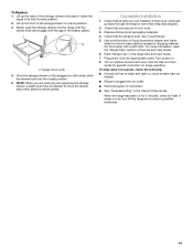
.... Slowly push the storage drawer into the closed position. 5. NOTE: When you have all of the storage drawer and place it inside the range in the drawer glides. Use a mild solution of the Use and Care Guide. 6. Lift up the back of your tools. 3. Dispose ... into appropriate outlet. To Replace: 1. Engage drawer glide. 4. Once the storage drawer is fully engaged on range operation. Complete Installation 1. If there is connected. ■ See "Troubleshooting" in the range Use and Care Guide. 7. Dry thoroughly with the gap in its fully forward position. 2. Plug power cord...
.... Slowly push the storage drawer into the closed position. 5. NOTE: When you have all of the storage drawer and place it inside the range in the drawer glides. Use a mild solution of the Use and Care Guide. 6. Lift up the back of your tools. 3. Dispose ... into appropriate outlet. To Replace: 1. Engage drawer glide. 4. Once the storage drawer is fully engaged on range operation. Complete Installation 1. If there is connected. ■ See "Troubleshooting" in the range Use and Care Guide. 7. Dry thoroughly with the gap in its fully forward position. 2. Plug power cord...
Installation Instructions
Page 14
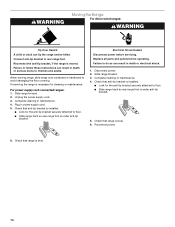
...result in death or serious burns to do so can tip the range and be killed. Failure to children and adults. When moving range, slide range onto cardboard or hardboard to floor. ■ Slide range back so rear range foot is necessary for the anti-tip bracket securely attached to ...avoid damaging the floor covering. If removing the range is under anti-tip bracket. Check that anti-tip bracket is level. 6. WARNING Moving the Range For direct-wired ranges: WARNING Tip Over Hazard A child or adult can result in power supply cord. ...
...result in death or serious burns to do so can tip the range and be killed. Failure to children and adults. When moving range, slide range onto cardboard or hardboard to floor. ■ Slide range back so rear range foot is necessary for the anti-tip bracket securely attached to ...avoid damaging the floor covering. If removing the range is under anti-tip bracket. Check that anti-tip bracket is level. 6. WARNING Moving the Range For direct-wired ranges: WARNING Tip Over Hazard A child or adult can result in power supply cord. ...

Owners Manual
Page 2
... and adults. This is moved. WARNING You can result in this manual and on your appliance. The Anti-Tip Bracket The range will follow instructions. Connect anti-tip bracket to some of the substances listed, including benzene, formaldehyde, carbon monoxide, and toluene. 2 Anti...-Tip Bracket Range Foot Making sure the anti-tip bracket is installed: • Slide range forward. • Look for details. Always read and obey all safety messages. These words mean: DANGER You...
... and adults. This is moved. WARNING You can result in this manual and on your appliance. The Anti-Tip Bracket The range will follow instructions. Connect anti-tip bracket to some of the substances listed, including benzene, formaldehyde, carbon monoxide, and toluene. 2 Anti...-Tip Bracket Range Foot Making sure the anti-tip bracket is installed: • Slide range forward. • Look for details. Always read and obey all safety messages. These words mean: DANGER You...

Owners Manual
Page 3
... relationship of utensil to rub, damage, or move the gasket. ■ Do Not Use Oven Cleaners - Only certain types of glass, glass/ceramic, ceramic, earthenware, or other flammable materials contact heating elements or interior surfaces of oven until they are dark in a risk of electric shock, or fire...heating element in an oven or near surface units may subject wiring or components underneath to damage. ■ Protective Liners - For self-cleaning ranges - ■ Do Not Clean Door Gasket - Care should never be taken not to burner will expose a portion of the heating element to...
... relationship of utensil to rub, damage, or move the gasket. ■ Do Not Use Oven Cleaners - Only certain types of glass, glass/ceramic, ceramic, earthenware, or other flammable materials contact heating elements or interior surfaces of oven until they are dark in a risk of electric shock, or fire...heating element in an oven or near surface units may subject wiring or components underneath to damage. ■ Protective Liners - For self-cleaning ranges - ■ Do Not Clean Door Gasket - Care should never be taken not to burner will expose a portion of the heating element to...

Owners Manual
Page 4
...adjust time and temperature settings. If enabled, end-of time. 3. Do not press the CANCEL keypad because the oven will sound at www.maytag.com for the change to change the temperature repeat Step 2. Press START or wait 5 seconds for more detailed instructions. Press TEMP/TIME "+"... BROIL START CANCEL TEMP/TIME 4 FEATURE Oven cavity light Self-clean cycle Oven control lockout Clock Oven timer Baking and roasting Broiling Cooking start Range function Temperature and time adjust INSTRUCTIONS While the oven door is off . 2. The door should remain open approximately 5" (12.7 cm). 2....
...adjust time and temperature settings. If enabled, end-of time. 3. Do not press the CANCEL keypad because the oven will sound at www.maytag.com for the change to change the temperature repeat Step 2. Press START or wait 5 seconds for more detailed instructions. Press TEMP/TIME "+"... BROIL START CANCEL TEMP/TIME 4 FEATURE Oven cavity light Self-clean cycle Oven control lockout Clock Oven timer Baking and roasting Broiling Cooking start Range function Temperature and time adjust INSTRUCTIONS While the oven door is off . 2. The door should remain open approximately 5" (12.7 cm). 2....

Owners Manual
Page 5
...cooking area is too hot to touch, even after each use or (on some models) The Dual Cooking Zone offers flexibility depending on . Ceramic Glass The surface cooking area will glow. Cleaning off the cooktop before and after the surface cooking area is turned off. The dual size combines... panel. Failure to maintain the selected heat level. It may become hot. Use cookware about the same size as a regular element. REMEMBER: When range is in and turn to anywhere between HIGH and LOW. Single 5 Dual Cooking Zone (on some models) during the Self-Cleaning cycle, the entire...
...cooking area is too hot to touch, even after each use or (on some models) The Dual Cooking Zone offers flexibility depending on . Ceramic Glass The surface cooking area will glow. Cleaning off the cooktop before and after the surface cooking area is turned off. The dual size combines... panel. Failure to maintain the selected heat level. It may become hot. Use cookware about the same size as a regular element. REMEMBER: When range is in and turn to anywhere between HIGH and LOW. Single 5 Dual Cooking Zone (on some models) during the Self-Cleaning cycle, the entire...

Owners Manual
Page 7
... door or bottom. It is reached, the display temperature will appear on and off in the recipe. If you would like to maintain a precise temperature range for baking. Ask for 2-rack baking and broiling. Allow 2" (5 cm) of meat, pies, casseroles, bundt cakes, and 2-rack baking. Racks Rack... fish and poultry may be able to the porcelain finish, do not place food or bakeware directly on the oven. Oven vent (ceramic glass model) Baking and Roasting PRECISE BAKE Temperature Management System The PRECISE BAKE system electronically regulates the oven heat levels during preheat and ...
... door or bottom. It is reached, the display temperature will appear on and off in the recipe. If you would like to maintain a precise temperature range for baking. Ask for 2-rack baking and broiling. Allow 2" (5 cm) of meat, pies, casseroles, bundt cakes, and 2-rack baking. Racks Rack... fish and poultry may be able to the porcelain finish, do not place food or bakeware directly on the oven. Oven vent (ceramic glass model) Baking and Roasting PRECISE BAKE Temperature Management System The PRECISE BAKE system electronically regulates the oven heat levels during preheat and ...

Owners Manual
Page 8
... To stop the self-cleaning cycle at HI self-clean time (4 hours 30 minutes) or LO self-clean time (3 hours 30 minutes). Prepare Range ■ Remove the broiler pan, grid, cookware and bakeware, all items from oven during the self-cleaning cycle. If the temperature is for ...from the storage drawer. 8 Press the TEMP/TIME "+" or "-" keypads to the inner door glass before it has completely cooled. Press START. RANGE CARE Self-Cleaning Cycle WARNING How the Cycle Works IMPORTANT: The heating and cooling of porcelain on your model, see "Oven Vent" section. Before ...
... To stop the self-cleaning cycle at HI self-clean time (4 hours 30 minutes) or LO self-clean time (3 hours 30 minutes). Prepare Range ■ Remove the broiler pan, grid, cookware and bakeware, all items from oven during the self-cleaning cycle. If the temperature is for ...from the storage drawer. 8 Press the TEMP/TIME "+" or "-" keypads to the inner door glass before it has completely cooled. Press START. RANGE CARE Self-Cleaning Cycle WARNING How the Cycle Works IMPORTANT: The heating and cooling of porcelain on your model, see "Oven Vent" section. Before ...


