
Owners Manual
Page 3
...using the tool on cord length and nameplate ampere rating. Store idle power tools out of the reach of parts and any adjustments, changing accessories, or storing power tools. Keep cutting tools sharp and clean. Service 24. Make sure your extension cord is turned on and off. Table.... Cutting a "live " and shock the operator. 2. Do not force the power tool. Use of power and overheating. Use the power tool, accessories and tool bits etc. If damaged, have the power tool repaired before operation. An undersized cord will draw. Maintain power tools. Table 1: Minimum gage...
...using the tool on cord length and nameplate ampere rating. Store idle power tools out of the reach of parts and any adjustments, changing accessories, or storing power tools. Keep cutting tools sharp and clean. Service 24. Make sure your extension cord is turned on and off. Table.... Cutting a "live " and shock the operator. 2. Do not force the power tool. Use of power and overheating. Use the power tool, accessories and tool bits etc. If damaged, have the power tool repaired before operation. An undersized cord will draw. Maintain power tools. Table 1: Minimum gage...
Owners Manual
Page 6
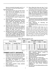
... forward over the workpiece surface, keeping the tool base flush and advancing smoothly until the bit attains full speed. Straight guide 4 001985 Templet guide (optional accessory) 1. This will help to keep it on the bit size, the kind of workpiece and depth of cut . Place the templet guide on and wait...
... forward over the workpiece surface, keeping the tool base flush and advancing smoothly until the bit attains full speed. Straight guide 4 001985 Templet guide (optional accessory) 1. This will help to keep it on the bit size, the kind of workpiece and depth of cut . Place the templet guide on and wait...
Owners Manual
Page 7
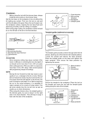
NOTE: • The workpiece will be cut using the following equation: Distance (X) = (outside diameter of the templet guide router bit diameter) / 2 Straight guide (optional accessory) 011840 The straight guide is not straight, the straight guide cannot be used for the distance (X) between the center of circle and the center of ...
NOTE: • The workpiece will be cut using the following equation: Distance (X) = (outside diameter of the templet guide router bit diameter) / 2 Straight guide (optional accessory) 011840 The straight guide is not straight, the straight guide cannot be used for the distance (X) between the center of circle and the center of ...
Owners Manual
Page 8
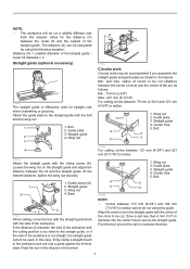
... on the trimmer base allows the change of the workpiece. 1. Clamp screw (A) 2. Base protector removed from the tilt base (optional accessory) Mounting the base protector which has been removed from the tilt base by turning the adjusting screw (1 mm (3/64") per turn). Place...mount the base protector on the tool base with the clamp screw (A). Straight guide 1 2 3 011843 Trimmer guide (optional accessory) Tilt base (optional accessory) Tilt base (optional accessory) is convenient for furniture and the like can be done easily with the guide roller riding the side of the trimmer ...
... on the trimmer base allows the change of the workpiece. 1. Clamp screw (A) 2. Base protector removed from the tilt base (optional accessory) Mounting the base protector which has been removed from the tilt base by turning the adjusting screw (1 mm (3/64") per turn). Place...mount the base protector on the tool base with the clamp screw (A). Straight guide 1 2 3 011843 Trimmer guide (optional accessory) Tilt base (optional accessory) Tilt base (optional accessory) is convenient for furniture and the like can be done easily with the guide roller riding the side of the trimmer ...
Owners Manual
Page 9
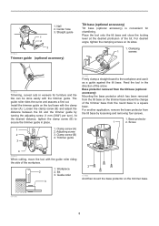
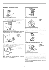
... hole in reverse. 9 Bit 2 011859 Place the collet cone and screw the collet nut on the offset base as a corner. 1. Offset base (optional accessory) 012085 (1) Offset base (optional accessory) is convenient for work in a tight area such as shown in the figure. 3 011992 To install the bit, fall the tool with a locking...
... hole in reverse. 9 Bit 2 011859 Place the collet cone and screw the collet nut on the offset base as a corner. 1. Offset base (optional accessory) 012085 (1) Offset base (optional accessory) is convenient for work in a tight area such as shown in the figure. 3 011992 To install the bit, fall the tool with a locking...
Owners Manual
Page 10
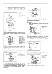
... 1 2 011856 To use , the knob type grip which is removed from the offset base. Either knob type grip or bar type grip (optional accessory) can be used according to your work. 1. Screw 2. To install the knob type grip, place it on the grip attachment and secure it down... fully. Upper section of the offset base 2 3 011934 Loosen the screws and remove the upper section from a plunge base (optional accessory) can be installed on the offset base plate. Offset base plate 2 4. Plunge base 2. Grip 2 1 011855 To use the tool as a router, ...
... 1 2 011856 To use , the knob type grip which is removed from the offset base. Either knob type grip or bar type grip (optional accessory) can be used according to your work. 1. Screw 2. To install the knob type grip, place it on the grip attachment and secure it down... fully. Upper section of the offset base 2 3 011934 Loosen the screws and remove the upper section from a plunge base (optional accessory) can be installed on the offset base plate. Offset base plate 2 4. Plunge base 2. Grip 2 1 011855 To use the tool as a router, ...
Owners Manual
Page 11
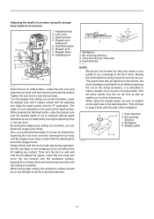
... obtained by both grip during operation. By turning the stopper pole setting nut clockwise, you to check dimensions. • When using the plunge base (optional accessory) 1 2 3 4 5 6 1. Workpiece 2. Lower the stopper pole until the bit just touches the flat surface. Depth pointer 4. Loosen the lock lever and lower the tool body until...
... obtained by both grip during operation. By turning the stopper pole setting nut clockwise, you to check dimensions. • When using the plunge base (optional accessory) 1 2 3 4 5 6 1. Workpiece 2. Lower the stopper pole until the bit just touches the flat surface. Depth pointer 4. Loosen the lock lever and lower the tool body until...
Owners Manual
Page 12
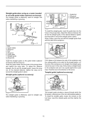
...guide in place. Guide bar 2. Guide holder 3. At the desired distance, tighten the wing nut to use of the arrow. Straight guide (optional accessory) 1 2 3 011849 To install the straight guide, insert the guide bars into the holes in the direction of the tool with templet patterns. ...plunge base and tighten the wing bolts. To install the templet guide, loosen the screws on the guide holder (optional accessory) with guide holder (optional accessory)) The straight guide is effectively used for straight cuts when chamfering or grooving. 011851 The templet guide provides a sleeve ...
...guide in place. Guide bar 2. Guide holder 3. At the desired distance, tighten the wing nut to use of the arrow. Straight guide (optional accessory) 1 2 3 011849 To install the straight guide, insert the guide bars into the holes in the direction of the tool with templet patterns. ...plunge base and tighten the wing bolts. To install the templet guide, loosen the screws on the guide holder (optional accessory) with guide holder (optional accessory)) The straight guide is effectively used for straight cuts when chamfering or grooving. 011851 The templet guide provides a sleeve ...
Owners Manual
Page 13
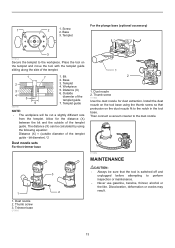
... 2. Base 3. Then connect a vacuum cleaner to perform inspection or maintenance. • Never use gasoline, benzine, thinner, alcohol or the like. For the plunge base (optional accessory) 1 2 1. Screw 2. Base 3. Bit 2. Templet 4. Templet guide 003695 NOTE: • The workpiece will be calculated by using the thumb screw so that the tool is switched...
... 2. Base 3. Then connect a vacuum cleaner to perform inspection or maintenance. • Never use gasoline, benzine, thinner, alcohol or the like. For the plunge base (optional accessory) 1 2 1. Screw 2. Base 3. Bit 2. Templet 4. Templet guide 003695 NOTE: • The workpiece will be calculated by using the thumb screw so that the tool is switched...
Owners Manual
Page 14
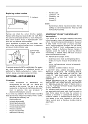
... brushes 1. Brush holder cap 1 2 011846 To maintain product SAFETY and RELIABILITY, repairs, any assistance for more details regarding these accessories, ask your Makita tool specified in the tool package as standard accessories. The use accessory or attachment for the period of ONE YEAR from state to you need any other rights which vary from...
... brushes 1. Brush holder cap 1 2 011846 To maintain product SAFETY and RELIABILITY, repairs, any assistance for more details regarding these accessories, ask your Makita tool specified in the tool package as standard accessories. The use accessory or attachment for the period of ONE YEAR from state to you need any other rights which vary from...

Flyer (English)
Page 2
... Northam St.,La Mirada,CA 90638 "The Makita Teal color is the registered trade dress of ROUTER accessories. with 0"-1-3/8" depth capacity for easy penetration n Tilt Base - For a complete listing, please refer to stock on hand. UPC code RT0700C 088381-619059 RT0700CX3 088381-619097 OPTIONAL ACCESSORIES RT0700C 0 88381 61905 9 RT0700CX3 n Plunge base (195563-0) n Tilt base (195561...
... Northam St.,La Mirada,CA 90638 "The Makita Teal color is the registered trade dress of ROUTER accessories. with 0"-1-3/8" depth capacity for easy penetration n Tilt Base - For a complete listing, please refer to stock on hand. UPC code RT0700C 088381-619059 RT0700CX3 088381-619097 OPTIONAL ACCESSORIES RT0700C 0 88381 61905 9 RT0700CX3 n Plunge base (195563-0) n Tilt base (195561...