
Owners Manual
Page 2
.... KEEP GUARDS IN PLACE and in damp or wet locations, or expose them t o rain. ALWAYS USE SAFETY GLASSES. Everyday eyeglasses only have read all times. 1 4 . It's safer than using your hand and it w a s designed. 9. U S E RECOMMENDED ACCESSORIES. REMOVE ADJUSTING KEYS AND... area. 7. Learn the tools applications and limitations, a s well a s the specific potential hazards peculiar to d o a job for recommended accessories. Use clamps or a vise t o hold work area well lighted. 6 . DON'T OVERREACH. KEEP CHILDREN AWAY. Form habit of injury t o persons. ...
.... KEEP GUARDS IN PLACE and in damp or wet locations, or expose them t o rain. ALWAYS USE SAFETY GLASSES. Everyday eyeglasses only have read all times. 1 4 . It's safer than using your hand and it w a s designed. 9. U S E RECOMMENDED ACCESSORIES. REMOVE ADJUSTING KEYS AND... area. 7. Learn the tools applications and limitations, a s well a s the specific potential hazards peculiar to d o a job for recommended accessories. Use clamps or a vise t o hold work area well lighted. 6 . DON'T OVERREACH. KEEP CHILDREN AWAY. Form habit of injury t o persons. ...

Owners Manual
Page 3
... cord immediately. CHECK DAMAGED PARTS. A guard or other part that is harmful t o the motor. 3 EXTENSION CORDS: Use only three-wire extension cords which have threeprong grounding-type plugs and three-pole receptacles which accept the tool's plug. NEVER... . Don't leave tool until it will operate properly and perform its operation. If in u s e t o protect the operator from electric shock. 23. 18. Using a power source with voltage greater than the nameplate rating is damaged should b e properly repaired or replaced. 20. NEVER STAND ON TOOL. DIRECTION OF FEED. VOLTAGE...
... cord immediately. CHECK DAMAGED PARTS. A guard or other part that is harmful t o the motor. 3 EXTENSION CORDS: Use only three-wire extension cords which have threeprong grounding-type plugs and three-pole receptacles which accept the tool's plug. NEVER... . Don't leave tool until it will operate properly and perform its operation. If in u s e t o protect the operator from electric shock. 23. 18. Using a power source with voltage greater than the nameplate rating is damaged should b e properly repaired or replaced. 20. NEVER STAND ON TOOL. DIRECTION OF FEED. VOLTAGE...

Owners Manual
Page 4
..., floor, etc., causing damage t o the cutter chain at the time of hole breakthrough. 6. Replace cracked or damaged cutter chain immediately. 7 . This tool is very sharp. 5. Use this tool only t o cut holes in flat-surfaced wood. ADDITIONAL SAFETY RULES 1 .
..., floor, etc., causing damage t o the cutter chain at the time of hole breakthrough. 6. Replace cracked or damaged cutter chain immediately. 7 . This tool is very sharp. 5. Use this tool only t o cut holes in flat-surfaced wood. ADDITIONAL SAFETY RULES 1 .

Owners Manual
Page 7
... also cause a dangerous reaction. Adjusting indicator plate and indication plate The yellow indicator plate and indication plate are factory adjusted for some reason, or when using another size cutter chain, loosen the screws and adjust the yellow indicator plate and indication plate. WARNING: Before plugging in the workpiece. After cutting, gently...
... also cause a dangerous reaction. Adjusting indicator plate and indication plate The yellow indicator plate and indication plate are factory adjusted for some reason, or when using another size cutter chain, loosen the screws and adjust the yellow indicator plate and indication plate. WARNING: Before plugging in the workpiece. After cutting, gently...

Owners Manual
Page 8
...bolts securing the gauge plate. Cut the first hole with the lever ( B ) pushed away from you. Example : When cutting a hole 25 mm (1") wide using a cutter chain 18 mm (23/32"). 2. A hole a little longer than predetermined may be determined in three steps shown in the No. 2 set position Hole...A hole can be cut depending upon the cutter chain tension. .The adjusting hex bolts are factory adjusted for cutting a hole 30 mm (1-3/16") wide using a cutter chain 18mm (23/32"), proceed as follows: Push the lever (B) away from you and cut again to be enlarged transversely by adjusting the...
...bolts securing the gauge plate. Cut the first hole with the lever ( B ) pushed away from you. Example : When cutting a hole 25 mm (1") wide using a cutter chain 18 mm (23/32"). 2. A hole a little longer than predetermined may be determined in three steps shown in the No. 2 set position Hole...A hole can be cut depending upon the cutter chain tension. .The adjusting hex bolts are factory adjusted for cutting a hole 30 mm (1-3/16") wide using a cutter chain 18mm (23/32"), proceed as follows: Push the lever (B) away from you and cut again to be enlarged transversely by adjusting the...

Owners Manual
Page 9
... the left -hand grip and move the cutter chain back to slip off the set position. When cutting a hole, first use the perpen- I Adjusting hex bolt -for No. 1 set Dosition WARNING: When using pressure to t u r n the adjusting hex bolt or hex n u t , be careful not to allow the adjusting hex bolt to its...
... the left -hand grip and move the cutter chain back to slip off the set position. When cutting a hole, first use the perpen- I Adjusting hex bolt -for No. 1 set Dosition WARNING: When using pressure to t u r n the adjusting hex bolt or hex n u t , be careful not to allow the adjusting hex bolt to its...

Owners Manual
Page 11
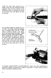
...the same time. Both carbon brushes should be sure that its hex head fits properly into the groove in the holders. Use only Makita carbon brushes. Limit mark Use a screwdriver to perform inspection or maintenance. Take out the worn carbon brushes, insert the new ones and secure the brush...the chain bar. Secure the sharpening holder to slip in the chain bar. Keep the carbon brushes clean and free to the chain bar using the wing nut and flatwasher (semi-tighten). Remove the adjusting screw from the sharpening holder assembly. I \ Cutter chain 11 Sharpening cutter ...
...the same time. Both carbon brushes should be sure that its hex head fits properly into the groove in the holders. Use only Makita carbon brushes. Limit mark Use a screwdriver to perform inspection or maintenance. Take out the worn carbon brushes, insert the new ones and secure the brush...the chain bar. Secure the sharpening holder to slip in the chain bar. Keep the carbon brushes clean and free to the chain bar using the wing nut and flatwasher (semi-tighten). Remove the adjusting screw from the sharpening holder assembly. I \ Cutter chain 11 Sharpening cutter ...
Owners Manual
Page 12
Use a grinder suitable for example, Makita Model 9300). Its no load speed should be careful to maintain the cutter chain configurations identical to be sharpened To maintain product SAFETY and RELIABILITY, ... and then oil the link portions. When sharpening, be 3,000 -3,600 RPM (for sharpening a cutter chain. Sharpen all cutters evenly, one by Makita Authorized or Factory Service Centers, always using Makita replacement parts. 12 Grinding wheel R 1.5mm (1/16") Portion to the original cutter chain. Install the cutter chain around this as shown in...
Use a grinder suitable for example, Makita Model 9300). Its no load speed should be careful to maintain the cutter chain configurations identical to be sharpened To maintain product SAFETY and RELIABILITY, ... and then oil the link portions. When sharpening, be 3,000 -3,600 RPM (for sharpening a cutter chain. Sharpen all cutters evenly, one by Makita Authorized or Factory Service Centers, always using Makita replacement parts. 12 Grinding wheel R 1.5mm (1/16") Portion to the original cutter chain. Install the cutter chain around this as shown in...

Owners Manual
Page 13
... spring washer, flat washer and hex nut. To install the sprocket for 30" (1-3/16"), mount the sprocket onto the spindle with your Makita tool specified in this manual. I 791085-4 I 7 9 1 0 8 6 - 2 I 79- 108-7-0 I To remove the standard-equipped sprocket, in . The ring 1 5 is not necessary when securing the... sprocket for 30 mm (1-3/16"). Remove the adjusting screw from the chain bar. Hex nut 13 The use with the round hole side facing in - ing screw on the chain bar for 30 mm (1-3/16"). sert a slotted screwdriver as shown in the proper...
... spring washer, flat washer and hex nut. To install the sprocket for 30" (1-3/16"), mount the sprocket onto the spindle with your Makita tool specified in this manual. I 791085-4 I 7 9 1 0 8 6 - 2 I 79- 108-7-0 I To remove the standard-equipped sprocket, in . The ring 1 5 is not necessary when securing the... sprocket for 30 mm (1-3/16"). Remove the adjusting screw from the chain bar. Hex nut 13 The use with the round hole side facing in - ing screw on the chain bar for 30 mm (1-3/16"). sert a slotted screwdriver as shown in the proper...

Flyer (English)
Page 2
...Wrench (782209-3) • Triangular Rule (762001-3) • Double Edged High Speed Steel Blades (B-02870) GUIDE RULE for accurate and maximum use 12-1/4" Planer Model KP312 RUBBERIZED FRONT HANDLE for comfort control and reduced operator fatigue LARGE EJECTION CHUTE POLY "V" BELT efficiently transfers power from ... Curved Base Planer Model 1002BA LARGE FRONT GRIP for two-handed control and fine depth adjustment LARGE CHIP EJECTION CHUTE LOCK ON BUTTON for continuous use of planing width 12-1/4" 1/8" 12,000 RPM 15.0 21-3/4" 33 ft. 39.7 lbs. 50.6 lbs. 088381 05088 3 1 6-3/4" Power...
...Wrench (782209-3) • Triangular Rule (762001-3) • Double Edged High Speed Steel Blades (B-02870) GUIDE RULE for accurate and maximum use 12-1/4" Planer Model KP312 RUBBERIZED FRONT HANDLE for comfort control and reduced operator fatigue LARGE EJECTION CHUTE POLY "V" BELT efficiently transfers power from ... Curved Base Planer Model 1002BA LARGE FRONT GRIP for two-handed control and fine depth adjustment LARGE CHIP EJECTION CHUTE LOCK ON BUTTON for continuous use of planing width 12-1/4" 1/8" 12,000 RPM 15.0 21-3/4" 33 ft. 39.7 lbs. 50.6 lbs. 088381 05088 3 1 6-3/4" Power...


