User Manual
Page 18
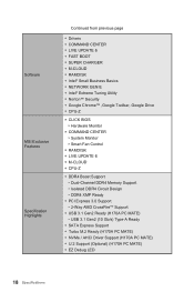
Software MSI Exclusive Features Specification Highlights Continued from previous page...9679; Norton™ Security ●● Google Chrome™ ,Google Toolbar, Google Drive ●● CPU-Z ●● CLICK BIOS ▶▶Hardware Monitor ●● COMMAND CENTER ▶▶System Monitor ...PC MATE) ▶▶USB 3.1 Gen2 (10 Gb/s) Type-A Ready ●● SATA Express Support ●● Turbo M.2 Ready (H170A PC MATE) ●● NVMe / AHCI Driver Support (H170A PC MATE) ●● U.2 Support (Optional) (H170A PC MATE) ●● EZ Debug LED...
Software MSI Exclusive Features Specification Highlights Continued from previous page...9679; Norton™ Security ●● Google Chrome™ ,Google Toolbar, Google Drive ●● CPU-Z ●● CLICK BIOS ▶▶Hardware Monitor ●● COMMAND CENTER ▶▶System Monitor ...PC MATE) ▶▶USB 3.1 Gen2 (10 Gb/s) Type-A Ready ●● SATA Express Support ●● Turbo M.2 Ready (H170A PC MATE) ●● NVMe / AHCI Driver Support (H170A PC MATE) ●● U.2 Support (Optional) (H170A PC MATE) ●● EZ Debug LED...

User Manual
Page 22
Overview of Components SYSFAN1 CPUFAN1 DIMM4 DIMM3 JPWR2 CPU Socket DIMM2 DIMM1 CPUFAN2 SYSFAN3 EZ Debug LED JPWR1 PCI_E1 M2_1 PCI_E2 PCI_E3 PCI_E4 JBAT1 PCI_E5 PCI1 PCI2 JUSB3 SE1_21 JCI1 SATA3_4 SATA5 SATA6 JAUD1 SYSFAN2 JCOM1 JFP1 JFP2 JUSB1 JUSB2 JLTP1 JTPM1 22 Overview of Components
Overview of Components SYSFAN1 CPUFAN1 DIMM4 DIMM3 JPWR2 CPU Socket DIMM2 DIMM1 CPUFAN2 SYSFAN3 EZ Debug LED JPWR1 PCI_E1 M2_1 PCI_E2 PCI_E3 PCI_E4 JBAT1 PCI_E5 PCI1 PCI2 JUSB3 SE1_21 JCI1 SATA3_4 SATA5 SATA6 JAUD1 SYSFAN2 JCOM1 JFP1 JFP2 JUSB1 JUSB2 JLTP1 JTPM1 22 Overview of Components
User Manual
Page 23
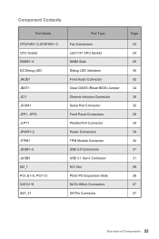
Component Contents Port Name CPUFAN1~2,SYSFAN1~3 CPU Socket DIMM1~4 EZ Debug LED JAUD1 JBAT1 JCI1 JCOM1 JFP1, JFP2 JLPT1 JPWR1~2 JTPM1 JUSB1~2 JUSB3 M2_1 PCI_E1~5, PCI1~2 SATA1~6 SE1_21 Port Type Fan Connectors LGA1151 CPU Socket DIMM Slots Debug LED indicators Front Audio Connector Clear CMOS (Reset BIOS) Jumper Chassis Intrusion Connector Serial Port Connector Front Panel Connectors Parallel...
Component Contents Port Name CPUFAN1~2,SYSFAN1~3 CPU Socket DIMM1~4 EZ Debug LED JAUD1 JBAT1 JCI1 JCOM1 JFP1, JFP2 JLPT1 JPWR1~2 JTPM1 JUSB1~2 JUSB3 M2_1 PCI_E1~5, PCI1~2 SATA1~6 SE1_21 Port Type Fan Connectors LGA1151 CPU Socket DIMM Slots Debug LED indicators Front Audio Connector Clear CMOS (Reset BIOS) Jumper Chassis Intrusion Connector Serial Port Connector Front Panel Connectors Parallel...
User Manual
Page 35
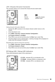
...to Enabled. 5. Go to the chassis intrusion switch/ sensor on . CPU - DRAM - VGA - Normal (default) Trigger the chassis intrusion event Using chassis intrusion detector 1. Connect the JCI1 connector to BIOS > Security > Chassis Intrusion Configuration. 4. EZ Debug LED: Debug LED indicators These LEDs indicate the status of Components 35 Press F10 to save and exit ... on screen when the computer is not detected or fail. Close the chassis cover. 3. indicates DRAM is not detected or fail. indicates CPU is turned on the chassis. 2. Set Chassis Intrusion to select Yes.
...to Enabled. 5. Go to the chassis intrusion switch/ sensor on . CPU - DRAM - VGA - Normal (default) Trigger the chassis intrusion event Using chassis intrusion detector 1. Connect the JCI1 connector to BIOS > Security > Chassis Intrusion Configuration. 4. EZ Debug LED: Debug LED indicators These LEDs indicate the status of Components 35 Press F10 to save and exit ... on screen when the computer is not detected or fail. Close the chassis cover. 3. indicates DRAM is not detected or fail. indicates CPU is turned on the chassis. 2. Set Chassis Intrusion to select Yes.

