User Guide
Page 5
Hardware Setup 2-1 Quick Components Guide 2-2 Central Processing Unit: CPU 2-3 CPU Core Speed Derivation Procedure 2-3 CPU Installation Procedures for Socket 478 2-5 Installing the CPU Fan 2-5 Memory 2-7 Introduction to DDR SDRAM 2-7 DDR Population Rules 2-7 Installing DDR Modules 2-8 Power Supply 2-9 ATX 20-Pin Power Connector: ATX1 2-9 v Getting Started 1-1 Mainboard Specifications 1-2 Mainboard Layout 1-4 MSI Special Features 1-5 Super Pack...
Hardware Setup 2-1 Quick Components Guide 2-2 Central Processing Unit: CPU 2-3 CPU Core Speed Derivation Procedure 2-3 CPU Installation Procedures for Socket 478 2-5 Installing the CPU Fan 2-5 Memory 2-7 Introduction to DDR SDRAM 2-7 DDR Population Rules 2-7 Installing DDR Modules 2-8 Power Supply 2-9 ATX 20-Pin Power Connector: ATX1 2-9 v Getting Started 1-1 Mainboard Specifications 1-2 Mainboard Layout 1-4 MSI Special Features 1-5 Super Pack...
User Guide
Page 15
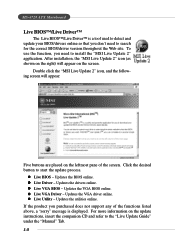
...- z Live Utility - Updates the drivers online. Updates the utilities online. MS-6728 ATX Mainboard Live BIOS™/Live Driver™ The Live BIOS™/Live Driver™ is displayed.... Click the desired button to the "Live Update Guide" under the "Manual" Tab. 1-8 z Live Driver - Updates the BIOS online. Updates the ...VGA BIOS online. For more information on the screen. z Live VGA BIOS - After installation, the "MSI Live Update 2" icon (as shown on the right) will appear: Five buttons are placed on the leftmost pane...
...- z Live Utility - Updates the drivers online. Updates the utilities online. MS-6728 ATX Mainboard Live BIOS™/Live Driver™ The Live BIOS™/Live Driver™ is displayed.... Click the desired button to the "Live Update Guide" under the "Manual" Tab. 1-8 z Live Driver - Updates the BIOS online. Updates the ...VGA BIOS online. For more information on the screen. z Live VGA BIOS - After installation, the "MSI Live Update 2" icon (as shown on the right) will appear: Five buttons are placed on the leftmost pane...
User Guide
Page 47
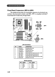
JFP1 is compliant with Intel® Front Panel I/O Connectivity Design Guide. 2-26 Reset HDD Switch LED 9 10 1 2 JFP1 Power Power Switch LED B ATT + Power LED 7 8 1 2 JFP2 Speaker JFP1 Pin Definition PIN SIGNAL 1 HD_LED_P 2 FP PWR/SLP 3 ... high reference pull-up Reset Switch high reference pull-up Power Switch low reference pull-down to the front panel switches and LEDs. MS-6728 ATX Mainboard Front Panel Connectors: JFP1 & JFP2 The mainboard provides two front panel connectors for electrical connection to GND Reserved. Do not use. JFP2 Pin Definition...
JFP1 is compliant with Intel® Front Panel I/O Connectivity Design Guide. 2-26 Reset HDD Switch LED 9 10 1 2 JFP1 Power Power Switch LED B ATT + Power LED 7 8 1 2 JFP2 Speaker JFP1 Pin Definition PIN SIGNAL 1 HD_LED_P 2 FP PWR/SLP 3 ... high reference pull-up Reset Switch high reference pull-up Power Switch low reference pull-down to the front panel switches and LEDs. MS-6728 ATX Mainboard Front Panel Connectors: JFP1 & JFP2 The mainboard provides two front panel connectors for electrical connection to GND Reserved. Do not use. JFP2 Pin Definition...
User Guide
Page 48
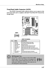
... audio signal to front panel 10 AUD_RET_L Left channel audio signal return from front panel MSI Reminds You... If you to connect to the front panel audio and is compliant with Intel® Front Panel I/O Connectivity Design Guide. Hardware Setup Front Panel Audio Connector: JAUD1 The JAUD1 front panel audio connector allows...
... audio signal to front panel 10 AUD_RET_L Left channel audio signal return from front panel MSI Reminds You... If you to connect to the front panel audio and is compliant with Intel® Front Panel I/O Connectivity Design Guide. Hardware Setup Front Panel Audio Connector: JAUD1 The JAUD1 front panel audio connector allows...
User Guide
Page 49
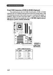
...- 5 USB0+ 6 USB1+ 7 GND 8 GND 9 Key (no pin) 10 USBOC 2 10 1 9 JUSB2, JUSB1 (USB 2.0/Intel spec) 2-28 MS-6728 ATX Mainboard Front USB Connectors: JUSB1 & JUSB2 (Optional) The mainboard provides two USB 2.0 pin headers JUSB1 & JUSB2 (Optional) that are compliant with Intel® I/O Connectivity ...Design Guide. USB 2.0 technology increases data transfer rate up to a maximum throughput of 480Mbps, which is 40 times faster than USB 1.1, and is...
...- 5 USB0+ 6 USB1+ 7 GND 8 GND 9 Key (no pin) 10 USBOC 2 10 1 9 JUSB2, JUSB1 (USB 2.0/Intel spec) 2-28 MS-6728 ATX Mainboard Front USB Connectors: JUSB1 & JUSB2 (Optional) The mainboard provides two USB 2.0 pin headers JUSB1 & JUSB2 (Optional) that are compliant with Intel® I/O Connectivity ...Design Guide. USB 2.0 technology increases data transfer rate up to a maximum throughput of 480Mbps, which is 40 times faster than USB 1.1, and is...
User Guide
Page 51
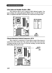
...GND 5 IRTX BATT + 6 IRRX JIR1 5 1 6 2 Chassis Intrusion Switch Connector: JCI1 This connector is compliant with Intel® Front Panel I/O Connectivity Design Guide. To clear the warning, you to connect to IrDA Infrared module. The system will be short. JIR1 is connected to a 2-pin chassis switch. MS-6728... ATX Mainboard IrDA Infrared Module Header: JIR1 The connector allows you must configure the setting through the BIOS setup to use the IR function....
...GND 5 IRTX BATT + 6 IRRX JIR1 5 1 6 2 Chassis Intrusion Switch Connector: JCI1 This connector is compliant with Intel® Front Panel I/O Connectivity Design Guide. To clear the warning, you to connect to IrDA Infrared module. The system will be short. JIR1 is connected to a 2-pin chassis switch. MS-6728... ATX Mainboard IrDA Infrared Module Header: JIR1 The connector allows you must configure the setting through the BIOS setup to use the IR function....
User Guide
Page 67
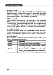
... the contents of the adapter ROM named in the item are not only copied to RAM, the contents of specified ROM are handled. MS-6728 ATX Mainboard APIC ACPI SCI IRQ This field is used to WriteBack will expand available IRQs resources for the system. The contents of the ROM area... mode. The setting controls the internal cache (also known as L1 or level 1 cache). Settings are copied to RAM. Due to compliance to PC2001 design guide, the system is much faster than conventional DRAM (system memory).
... the contents of the adapter ROM named in the item are not only copied to RAM, the contents of specified ROM are handled. MS-6728 ATX Mainboard APIC ACPI SCI IRQ This field is used to WriteBack will expand available IRQs resources for the system. The contents of the ROM area... mode. The setting controls the internal cache (also known as L1 or level 1 cache). Settings are copied to RAM. Due to compliance to PC2001 design guide, the system is much faster than conventional DRAM (system memory).
