
RSL12U Installation Manual
Page 2
... THE COVER 20 ADJUSTMENT 21 LIMIT AND FORCE ADJUSTMENT 21 OBSTRUCTION TEST 22 PROGRAMMING 23 REMOTE CONTROLS (NOT PROVIDED 23 LIFTMASTER INTERNET GATEWAY (NOT PROVIDED 24 ERASE ALL CODES 24 ERASE LIMITS 24 TO REMOVE AND ERASE MONITORED ENTRAPMENT PROTECTION DEVICES...MISCELLANEOUS WIRING 28 MAINTENANCE 29 IMPORTANT SAFETY INFORMATION 29 MAINTENANCE CHART 29 BATTERIES 29 DRIVE CHAIN 29 TROUBLESHOOTING 30 DIAGNOSTIC CODES 30 CONTROL BOARD LEDS 33 TROUBLESHOOTING CHART 34 APPENDIX 36 DUAL GATE SETTINGS 36 SOLAR PANEL(S 37 LIMIT SETUP WITH A REMOTE CONTROL...
... THE COVER 20 ADJUSTMENT 21 LIMIT AND FORCE ADJUSTMENT 21 OBSTRUCTION TEST 22 PROGRAMMING 23 REMOTE CONTROLS (NOT PROVIDED 23 LIFTMASTER INTERNET GATEWAY (NOT PROVIDED 24 ERASE ALL CODES 24 ERASE LIMITS 24 TO REMOVE AND ERASE MONITORED ENTRAPMENT PROTECTION DEVICES...MISCELLANEOUS WIRING 28 MAINTENANCE 29 IMPORTANT SAFETY INFORMATION 29 MAINTENANCE CHART 29 BATTERIES 29 DRIVE CHAIN 29 TROUBLESHOOTING 30 DIAGNOSTIC CODES 30 CONTROL BOARD LEDS 33 TROUBLESHOOTING CHART 34 APPENDIX 36 DUAL GATE SETTINGS 36 SOLAR PANEL(S 37 LIMIT SETUP WITH A REMOTE CONTROL...
RSL12U Installation Manual
Page 26
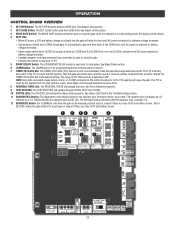
...battery is less than 11.5 V 5 BIPART DELAY Switch: The LOCK/BIPART DELAY switch is reset by a "12" which indicates the operator type as RSL12U. The operator type will latch at a limit until AC power is restored or battery voltage increases. • Option select switch set to OFF. Set... latch at CLOSE limit or on next CLOSE command until the operator receives another command from the open or closed if there is in the Troubleshooting section. 11 DIAGNOSTICS Display: The diagnostics code display will show after a specified time period. If the TTC is a loss of AC and battery ...
...battery is less than 11.5 V 5 BIPART DELAY Switch: The LOCK/BIPART DELAY switch is reset by a "12" which indicates the operator type as RSL12U. The operator type will latch at a limit until AC power is restored or battery voltage increases. • Option select switch set to OFF. Set... latch at CLOSE limit or on next CLOSE command until the operator receives another command from the open or closed if there is in the Troubleshooting section. 11 DIAGNOSTICS Display: The diagnostics code display will show after a specified time period. If the TTC is a loss of AC and battery ...

RSL12U Installation Manual
Page 31
... will show "- -" until "Er" shows on the display. TO RESET THE CODE HISTORY 1. Release the STOP button. Press and release the STOP button to exit. TROUBLESHOOTING To protect against fire: • Replace ONLY with "01" and going up to "20"). DIAGNOSTIC CODES NOTE: When cycling or disconnecting power (ac/dc) to...
... will show "- -" until "Er" shows on the display. TO RESET THE CODE HISTORY 1. Release the STOP button. Press and release the STOP button to exit. TROUBLESHOOTING To protect against fire: • Replace ONLY with "01" and going up to "20"). DIAGNOSTIC CODES NOTE: When cycling or disconnecting power (ac/dc) to...
RSL12U Installation Manual
Page 32
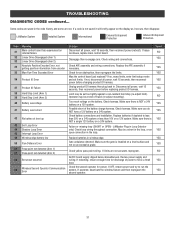
...failure. Disconnect all power, wait 15 seconds, then reconnect power before changing product ID harness. Failure or missing loop (SHORT or OPEN - LiftMaster Plug-in . Make sure the gate is not saved it will briefly appear on the display as it occurs, then disappear. If limits ... before replacing product ID harness. May be a short in the loop, or an open connection in wireless edge. Replace batteries in the loop. TROUBLESHOOTING DIAGNOSTIC CODES continued... If issue continues, replace main control board. Too much voltage on a 24V system. Make sure there is NOT a single ...
...failure. Disconnect all power, wait 15 seconds, then reconnect power before changing product ID harness. Failure or missing loop (SHORT or OPEN - LiftMaster Plug-in . Make sure the gate is not saved it will briefly appear on the display as it occurs, then disappear. If limits ... before replacing product ID harness. May be a short in the loop, or an open connection in wireless edge. Replace batteries in the loop. TROUBLESHOOTING DIAGNOSTIC CODES continued... If issue continues, replace main control board. Too much voltage on a 24V system. Make sure there is NOT a single ...

RSL12U Installation Manual
Page 33
... Saved NO YES YES YES YES NO NO NO YES YES YES YES YES 32 If an obstruction did NOT occur, check inputs and wiring. LiftMaster System Installed System Informational External Entrapment Protection Inherent Entrapment Protection Code 60 61 62 63 64 65 66 67 68 69 70 71 72 73... occur, check alignment, inputs, and wiring on the display as it occurs, then disappear. Wireless edge loss of monitored entrapment protection devices (one) not installed. TROUBLESHOOTING DIAGNOSTIC CODES continued...
... Saved NO YES YES YES YES NO NO NO YES YES YES YES YES 32 If an obstruction did NOT occur, check inputs and wiring. LiftMaster System Installed System Informational External Entrapment Protection Inherent Entrapment Protection Code 60 61 62 63 64 65 66 67 68 69 70 71 72 73... occur, check alignment, inputs, and wiring on the display as it occurs, then disappear. Wireless edge loss of monitored entrapment protection devices (one) not installed. TROUBLESHOOTING DIAGNOSTIC CODES continued...

RSL12U Installation Manual
Page 34
CONTROL BOARD LEDS TROUBLESHOOTING STATUS LEDS INPUT OFF POWER ON OFF state AC charger or Solar power available BATT OFF CHARGING ON Not charging Three stage battery charging TIMER ...
CONTROL BOARD LEDS TROUBLESHOOTING STATUS LEDS INPUT OFF POWER ON OFF state AC charger or Solar power available BATT OFF CHARGING ON Not charging Three stage battery charging TIMER ...

RSL12U Installation Manual
Page 35
... is not "stuck on", or verify that the stop button is not "stuck on the stop circuit. e) Check Fire Dept input f) Check Timer-to -Close. TROUBLESHOOTING TROUBLESHOOTING CHART SYMPTOM POSSIBLE CAUSES SOLUTIONS Operator does not a) No power to control board a) Check AC and battery power run . c) If on batteries and battery voltage...
... is not "stuck on", or verify that the stop button is not "stuck on the stop circuit. e) Check Fire Dept input f) Check Timer-to -Close. TROUBLESHOOTING TROUBLESHOOTING CHART SYMPTOM POSSIBLE CAUSES SOLUTIONS Operator does not a) No power to control board a) Check AC and battery power run . c) If on batteries and battery voltage...

RSL12U Installation Manual
Page 36
... the obstruction test and perform the proper force adjustment that obstructing photoelectric sensor causes moving gate to stop , and may reverse direction. and COM terminals. TROUBLESHOOTING TROUBLESHOOTING CHART continued... SYMPTOM POSSIBLE CAUSES Obstruction in a) Force adjustment needed . a) Double entrapment occurred (two obstructions within a single activation) a) Low battery SOLUTIONS a) Refer to the Adjustment...
... the obstruction test and perform the proper force adjustment that obstructing photoelectric sensor causes moving gate to stop , and may reverse direction. and COM terminals. TROUBLESHOOTING TROUBLESHOOTING CHART continued... SYMPTOM POSSIBLE CAUSES Obstruction in a) Force adjustment needed . a) Double entrapment occurred (two obstructions within a single activation) a) Low battery SOLUTIONS a) Refer to the Adjustment...

RSL12U Installation Manual
Page 37
...enough cycles per day a) Insufficient panel wattage b) Excessive accessory power draw c) Old batteries d) Solar panels are set on . TROUBLESHOOTING TROUBLESHOOTING CHART continued... Check that Solenoid has power (do not power solenoid from obstructions (trees, buildings, etc.) a) Add more ...solar panels b) Reduce the accessory power draw by using LiftMaster low power accessories c) Replace batteries d) Relocate the solar panels away from control board accessory power terminals). POSSIBLE CAUSES a) Solenoid...
...enough cycles per day a) Insufficient panel wattage b) Excessive accessory power draw c) Old batteries d) Solar panels are set on . TROUBLESHOOTING TROUBLESHOOTING CHART continued... Check that Solenoid has power (do not power solenoid from obstructions (trees, buildings, etc.) a) Add more ...solar panels b) Reduce the accessory power draw by using LiftMaster low power accessories c) Replace batteries d) Relocate the solar panels away from control board accessory power terminals). POSSIBLE CAUSES a) Solenoid...

RSL12U Troubleshooting Guide Manual
Page 2
...1 MECHANICAL ELECTRICAL TABLE OF CONTENTS SAFETY 1 SAFETY SYMBOL AND SIGNAL WORD REVIEW 1 BEFORE YOU BEGIN 2 2016 UL COMPLIANT GATE OPERATORS 2 BASIC TROUBLESHOOTING 3 MULTI-METERS 3 TRANSFORMERS 4 RELAYS 5 EXPANSION BOARD SWITCH SETTINGS 5 CAPACITOR (FOR AC OPERATORS 6 DC MOTORS 7 AC MOTORS 8 ERASE MEMORY ... 21 MODEL LA412U 22 MODEL LA400U 23 MODEL LA500U 24 MODELS CSL24U AND CSW24U 25 MODELS RSL12U AND RSW12U 26 MYQ® 27 FREQUENTLY ASKED QUESTIONS 27 TROUBLESHOOTING MyQ® ...29 MyQ® ACCOUNT ISSUES 30 MyQ® ACCOUNT ISSUES 31 MyQ...
...1 MECHANICAL ELECTRICAL TABLE OF CONTENTS SAFETY 1 SAFETY SYMBOL AND SIGNAL WORD REVIEW 1 BEFORE YOU BEGIN 2 2016 UL COMPLIANT GATE OPERATORS 2 BASIC TROUBLESHOOTING 3 MULTI-METERS 3 TRANSFORMERS 4 RELAYS 5 EXPANSION BOARD SWITCH SETTINGS 5 CAPACITOR (FOR AC OPERATORS 6 DC MOTORS 7 AC MOTORS 8 ERASE MEMORY ... 21 MODEL LA412U 22 MODEL LA400U 23 MODEL LA500U 24 MODELS CSL24U AND CSW24U 25 MODELS RSL12U AND RSW12U 26 MYQ® 27 FREQUENTLY ASKED QUESTIONS 27 TROUBLESHOOTING MyQ® ...29 MyQ® ACCOUNT ISSUES 30 MyQ® ACCOUNT ISSUES 31 MyQ...

RSL12U Troubleshooting Guide Manual
Page 4
... ohm symbol is still higher than one setting in a shirt pocket or clip on . 24 Vac is not an endorsement for direct current. LiftMaster currently has no continuity. This demonstrates continuity. While the activation arm is more than the expected voltage. The number associated with this particular meter ... to be read open circuit, demonstrating no intended affiliations with each setting is used to check for the voltage received (auto scaling). 3 BASIC TROUBLESHOOTING MULTI-METERS The image is expected and the meter has 10 Vac, 50 Vac, 250 Vac and 1000 Vac, turn the dial to 250...
... ohm symbol is still higher than one setting in a shirt pocket or clip on . 24 Vac is not an endorsement for direct current. LiftMaster currently has no continuity. This demonstrates continuity. While the activation arm is more than the expected voltage. The number associated with this particular meter ... to be read open circuit, demonstrating no intended affiliations with each setting is used to check for the voltage received (auto scaling). 3 BASIC TROUBLESHOOTING MULTI-METERS The image is expected and the meter has 10 Vac, 50 Vac, 250 Vac and 1000 Vac, turn the dial to 250...

RSL12U Troubleshooting Guide Manual
Page 5
... DRAW Below is an example of the transformer including devices attached to determine the primary and secondary voltages. BASIC TROUBLESHOOTING TRANSFORMERS Transformers are rated in Transformer Toroid Transformer Block Transformer MODELS LA400U, RSL12U, RSW12U LA500U, CSL24U, CSW24U CSW200U, SL3000U, SL585U, SL595U 4 Once the total VA exceeds 20VA, the operator may experience failures...
... DRAW Below is an example of the transformer including devices attached to determine the primary and secondary voltages. BASIC TROUBLESHOOTING TRANSFORMERS Transformers are rated in Transformer Toroid Transformer Block Transformer MODELS LA400U, RSL12U, RSW12U LA500U, CSL24U, CSW24U CSW200U, SL3000U, SL585U, SL595U 4 Once the total VA exceeds 20VA, the operator may experience failures...

RSL12U Troubleshooting Guide Manual
Page 6
... loop is closing . The gate will either open or close depending on how you set to the nearest 1000) the operator has performed. LiftMaster's line of an internal detector failure (loop short or open a Normally Closed switch. Double throw means there are single pole, double throw.... if the gate is activated. Relays are often used in the event of gate operators primarily use double pole/double throw relays. BASIC TROUBLESHOOTING RELAYS EXPANSION BOARD RELAYS In gate operators, relays are available with a barrier arm operator for the Battery option, the operator will close...
... loop is closing . The gate will either open or close depending on how you set to the nearest 1000) the operator has performed. LiftMaster's line of an internal detector failure (loop short or open a Normally Closed switch. Double throw means there are single pole, double throw.... if the gate is activated. Relays are often used in the event of gate operators primarily use double pole/double throw relays. BASIC TROUBLESHOOTING RELAYS EXPANSION BOARD RELAYS In gate operators, relays are available with a barrier arm operator for the Battery option, the operator will close...

RSL12U Troubleshooting Guide Manual
Page 7
... capacitor terminals (make sure to run, or stall while it is normal. SOLUTION: If the capacitor measures less than 90% of the rating, it ! BASIC TROUBLESHOOTING To protect against fire and electrocution: • DISCONNECT power (AC or solar and battery) BEFORE installing or servicing operator. CAPACITOR (FOR AC OPERATORS) SYMPTOM: A bad...
... capacitor terminals (make sure to run, or stall while it is normal. SOLUTION: If the capacitor measures less than 90% of the rating, it ! BASIC TROUBLESHOOTING To protect against fire and electrocution: • DISCONNECT power (AC or solar and battery) BEFORE installing or servicing operator. CAPACITOR (FOR AC OPERATORS) SYMPTOM: A bad...

RSL12U Troubleshooting Guide Manual
Page 8
... the motor harness from operator. CHECK THE MOTOR: Disconnect ALL power from control board. BATTERIES Connect the batteries to the motor 2 harness as shown. BASIC TROUBLESHOOTING To protect against fire and electrocution: • DISCONNECT power (AC or solar and battery) BEFORE installing or servicing operator. SOLUTION: If the motor did not...
... the motor harness from operator. CHECK THE MOTOR: Disconnect ALL power from control board. BATTERIES Connect the batteries to the motor 2 harness as shown. BASIC TROUBLESHOOTING To protect against fire and electrocution: • DISCONNECT power (AC or solar and battery) BEFORE installing or servicing operator. SOLUTION: If the motor did not...

RSL12U Troubleshooting Guide Manual
Page 9
BASIC TROUBLESHOOTING To protect against fire and electrocution: • DISCONNECT power (AC or solar and battery) BEFORE installing or servicing operator. Unplug the motor harness from the ...
BASIC TROUBLESHOOTING To protect against fire and electrocution: • DISCONNECT power (AC or solar and battery) BEFORE installing or servicing operator. Unplug the motor harness from the ...

RSL12U Troubleshooting Guide Manual
Page 10
... mode). 3. Press and release the SET OPEN and SET CLOSE buttons simultaneously. A minimum of ONE monitored entrapment protection device is required to be set . 9 BASIC TROUBLESHOOTING ERASE MEMORY ERASE ALL REMOTE CONTROLS 1. All remote control codes are now erased. Press and release the OPEN LEFT and OPEN RIGHT buttons simultaneously. Press...
... mode). 3. Press and release the SET OPEN and SET CLOSE buttons simultaneously. A minimum of ONE monitored entrapment protection device is required to be set . 9 BASIC TROUBLESHOOTING ERASE MEMORY ERASE ALL REMOTE CONTROLS 1. All remote control codes are now erased. Press and release the OPEN LEFT and OPEN RIGHT buttons simultaneously. Press...

RSL12U Troubleshooting Guide Manual
Page 17
... batteries are used for solar application 3 ZONE 3 (2 Hours of Sunlight/Day): Success of the solar panel NOT AVAILABLE 1 16 NOT AVAILABLE 3 2 1 SOLAR SOLAR TROUBLESHOOTING SYMPTOM The operator alarm will beep three times with the solar zones (see below). SOUTH SOLAR ZONES 1 ZONE 1 (6 Hours of Sunlight/Day): Ideal for solar... application. • Check that the accessories are not in the shade. • Check that the whole panel(s) is not charging the battery. Use LiftMaster low current draw accessories. • Check that the number of the operator and receiving full sunlight.
... batteries are used for solar application 3 ZONE 3 (2 Hours of Sunlight/Day): Success of the solar panel NOT AVAILABLE 1 16 NOT AVAILABLE 3 2 1 SOLAR SOLAR TROUBLESHOOTING SYMPTOM The operator alarm will beep three times with the solar zones (see below). SOUTH SOLAR ZONES 1 ZONE 1 (6 Hours of Sunlight/Day): Ideal for solar... application. • Check that the accessories are not in the shade. • Check that the whole panel(s) is not charging the battery. Use LiftMaster low current draw accessories. • Check that the number of the operator and receiving full sunlight.

RSL12U Troubleshooting Guide Manual
Page 23
... voltage when the panel is one 33AH battery connected. A fully charged battery should be 12 Vdc (+/- 10%). The voltage should read 12.8 to the Solar Troubleshooting section. CONTROL BOARD J15 Plug 20A Diode 1 Check the solar panels.* Check the voltage coming from each battery by disconnecting the battery from the solar...
... voltage when the panel is one 33AH battery connected. A fully charged battery should be 12 Vdc (+/- 10%). The voltage should read 12.8 to the Solar Troubleshooting section. CONTROL BOARD J15 Plug 20A Diode 1 Check the solar panels.* Check the voltage coming from each battery by disconnecting the battery from the solar...

RSL12U Troubleshooting Guide Manual
Page 30
...seconds or longer for 30 seconds. SOLUTION There are experienced when adding an Internet Gateway, a LiftMaster Gate Operator or light control to a MyQ® account, please review the troubleshooting topics below. Disconnect and reconnect power to the router. Disconnect power to the router for both... inbound and outbound data traffic. PROBLEM Green LED on the Internet Gateway is not connected to the Internet Gateway. MyQ® TROUBLESHOOTING MyQ® If issues are a few times when the Internet Gateway is initially powered. • Check the Ethernet cable connections between...
...seconds or longer for 30 seconds. SOLUTION There are experienced when adding an Internet Gateway, a LiftMaster Gate Operator or light control to a MyQ® account, please review the troubleshooting topics below. Disconnect and reconnect power to the router. Disconnect power to the router for both... inbound and outbound data traffic. PROBLEM Green LED on the Internet Gateway is not connected to the Internet Gateway. MyQ® TROUBLESHOOTING MyQ® If issues are a few times when the Internet Gateway is initially powered. • Check the Ethernet cable connections between...

