CSL24U Sell Sheet Manual
Page 1
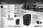
... Safety Entrapment Devices provide peace of mind for every gate application. All Rights Reserved. 845 Larch Ave., Elmhurst, IL 60126 LiftMaster.com LMGTBRCSLU 8/15 CONSTRUCTION P3 MOTOR® 24VDC continuous-duty motor. RECOMMENDED CAPACITIES Rated for rust prevention. Universal Single and ... Heater (HTR): -40°F (-40°C) to maximize solar performance. 24VDC High-Traffic Commercial Slide Gate Operator CSL24U FEATURES LED DIAGNOSTIC DISPLAY Simplifies installation and troubleshooting. WORM GEAR REDUCTION Commercial oil bath gearbox providing 10:1 worm gear reduction.
... Safety Entrapment Devices provide peace of mind for every gate application. All Rights Reserved. 845 Larch Ave., Elmhurst, IL 60126 LiftMaster.com LMGTBRCSLU 8/15 CONSTRUCTION P3 MOTOR® 24VDC continuous-duty motor. RECOMMENDED CAPACITIES Rated for rust prevention. Universal Single and ... Heater (HTR): -40°F (-40°C) to maximize solar performance. 24VDC High-Traffic Commercial Slide Gate Operator CSL24U FEATURES LED DIAGNOSTIC DISPLAY Simplifies installation and troubleshooting. WORM GEAR REDUCTION Commercial oil bath gearbox providing 10:1 worm gear reduction.
CSL24U Installation Manual
Page 3
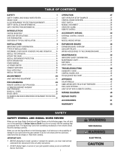
...GATES ONLY 20 INSTALL THE COVER 22 ADJUSTMENT 23 LIMIT AND FORCE ADJUSTMENT 23 PROGRAMMING 25 REMOTE CONTROLS (NOT PROVIDED 25 LIFTMASTER INTERNET GATEWAY (NOT PROVIDED 26 ERASE ALL CODES 26 ERASE LIMITS 26 TO REMOVE AND ERASE MONITORED ENTRAPMENT PROTECTION DEVICES ...EXPANSION BOARD 34 MAINTENANCE 35 IMPORTANT SAFETY INFORMATION 35 MAINTENANCE CHART 35 BATTERIES 35 DRIVE CHAIN 35 TROUBLESHOOTING 36 DIAGNOSTIC CODES 36 CONTROL BOARD LEDS 39 TROUBLESHOOTING CHART 40 APPENDIX 43 SOLAR PANEL(S 43 SAMS WIRING WITH RELAYS NOT ENERGIZED 47 DUAL GATE ...
...GATES ONLY 20 INSTALL THE COVER 22 ADJUSTMENT 23 LIMIT AND FORCE ADJUSTMENT 23 PROGRAMMING 25 REMOTE CONTROLS (NOT PROVIDED 25 LIFTMASTER INTERNET GATEWAY (NOT PROVIDED 26 ERASE ALL CODES 26 ERASE LIMITS 26 TO REMOVE AND ERASE MONITORED ENTRAPMENT PROTECTION DEVICES ...EXPANSION BOARD 34 MAINTENANCE 35 IMPORTANT SAFETY INFORMATION 35 MAINTENANCE CHART 35 BATTERIES 35 DRIVE CHAIN 35 TROUBLESHOOTING 36 DIAGNOSTIC CODES 36 CONTROL BOARD LEDS 39 TROUBLESHOOTING CHART 40 APPENDIX 43 SOLAR PANEL(S 43 SAMS WIRING WITH RELAYS NOT ENERGIZED 47 DUAL GATE ...

CSL24U Installation Manual
Page 30
...on a hard command input overrides to the OFF position, then the gate will show after a specified time period. The TTC is in the Troubleshooting section. 11 DIAGNOSTICS Display: The diagnostics display will remain open until the operator receives another command from the open and then latch at CLOSE ... is factory set to the TTC expiring will close the gate when the operator is reset by a "24" which indicates the operator type as CSL24U. The firmware version will show the operator type, firmware version, and codes. Rotate the TIMER-TO-CLOSE dial to be set to MANUAL will ...
...on a hard command input overrides to the OFF position, then the gate will show after a specified time period. The TTC is in the Troubleshooting section. 11 DIAGNOSTICS Display: The diagnostics display will remain open until the operator receives another command from the open and then latch at CLOSE ... is factory set to the TTC expiring will close the gate when the operator is reset by a "24" which indicates the operator type as CSL24U. The firmware version will show the operator type, firmware version, and codes. Rotate the TIMER-TO-CLOSE dial to be set to MANUAL will ...

CSL24U Installation Manual
Page 38
... as new codes occur. Press and hold the OPEN button until a new code occurs. 3. The operator will show on the following page for six seconds. TROUBLESHOOTING To protect against fire: • Replace ONLY with "01" and going up to "20"). For continued protection against fire and electrocution: • DISCONNECT power (AC...
... as new codes occur. Press and hold the OPEN button until a new code occurs. 3. The operator will show on the following page for six seconds. TROUBLESHOOTING To protect against fire: • Replace ONLY with "01" and going up to "20"). For continued protection against fire and electrocution: • DISCONNECT power (AC...
CSL24U Installation Manual
Page 39
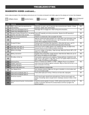
... 24V system or less than 10V on an excessive grade. Make sure there is installed on a level surface and not on a 12V system. LiftMaster Plug-in wireless edge. Wireless edge battery low Replace batteries in Loop Detector only) Check loop wiring throughout connection. If powered, deactivate the wireless ... obstruction, then reprogram the limits. Review power supply and wiring. Battery overcurrent Possible short of power to run the Error system. TROUBLESHOOTING DIAGNOSTIC CODES continued... Some codes are saved in the code history and some are not accurate, reprogram.
... 24V system or less than 10V on an excessive grade. Make sure there is installed on a level surface and not on a 12V system. LiftMaster Plug-in wireless edge. Wireless edge battery low Replace batteries in Loop Detector only) Check loop wiring throughout connection. If powered, deactivate the wireless ... obstruction, then reprogram the limits. Review power supply and wiring. Battery overcurrent Possible short of power to run the Error system. TROUBLESHOOTING DIAGNOSTIC CODES continued... Some codes are saved in the code history and some are not accurate, reprogram.

CSL24U Installation Manual
Page 40
...assembly is not saved it occurs, then disappear. Replace APE assembly. If a code is engaged and free to move . LiftMaster System Installed System Informational External Entrapment Protection Inherent Entrapment Protection Code 60 61 62 63 64 65 66 67 68 69 70 71... Some codes are saved in the code history and some are not. If no obstruction, check that the mechanical assembly is powered. TROUBLESHOOTING DIAGNOSTIC CODES continued... Review monitored entrapment protection device connections. If an obstruction did NOT occur, check alignment, inputs, and wiring on main...
...assembly is not saved it occurs, then disappear. Replace APE assembly. If a code is engaged and free to move . LiftMaster System Installed System Informational External Entrapment Protection Inherent Entrapment Protection Code 60 61 62 63 64 65 66 67 68 69 70 71... Some codes are saved in the code history and some are not. If no obstruction, check that the mechanical assembly is powered. TROUBLESHOOTING DIAGNOSTIC CODES continued... Review monitored entrapment protection device connections. If an obstruction did NOT occur, check alignment, inputs, and wiring on main...

CSL24U Installation Manual
Page 41
TROUBLESHOOTING CONTROL BOARD LEDS STATUS LEDS INPUT OFF POWER ON OFF state AC charger or Solar power available BATT OFF CHARGING ON Not charging Three stage ...
TROUBLESHOOTING CONTROL BOARD LEDS STATUS LEDS INPUT OFF POWER ON OFF state AC charger or Solar power available BATT OFF CHARGING ON Not charging Three stage ...
CSL24U Installation Manual
Page 42
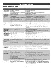
.... a) Open control active b) Vehicle loop detector active c) Loss of operator. e) Check Fire Dept input f) Check Timer-to control board a) Check AC and battery power run . TROUBLESHOOTING TROUBLESHOOTING CHART SYMPTOM POSSIBLE CAUSES SOLUTIONS Operator does not a) No power to -Close (TTC) setting g) Check all Entrapment Protection Device inputs for an active sensor a) Check...
.... a) Open control active b) Vehicle loop detector active c) Loss of operator. e) Check Fire Dept input f) Check Timer-to control board a) Check AC and battery power run . TROUBLESHOOTING TROUBLESHOOTING CHART SYMPTOM POSSIBLE CAUSES SOLUTIONS Operator does not a) No power to -Close (TTC) setting g) Check all Entrapment Protection Device inputs for an active sensor a) Check...

CSL24U Installation Manual
Page 43
... battery voltage must be 23.0 Vdc or higher. a) Review Interrupt loop detector settings. a) Check if AC power is available. Alarm beeps three times with a command. TROUBLESHOOTING TROUBLESHOOTING CHART continued...
... battery voltage must be 23.0 Vdc or higher. a) Review Interrupt loop detector settings. a) Check if AC power is available. Alarm beeps three times with a command. TROUBLESHOOTING TROUBLESHOOTING CHART continued...

CSL24U Installation Manual
Page 44
...Check that Solenoid has power (do not power solenoid from obstructions (trees, buildings, etc.) a) Add more solar panels b) Reduce the accessory power draw by using LiftMaster low power accessories c) Replace batteries d) Relocate the solar panels away from control board accessory power terminals). and COM. a) In limit setup mode Accessories connected to ...SYMPTOM Solenoid lock not working correctly. Replace defective expansion board. and COM terminals. If voltage is connected to Accessory power not working correctly. TROUBLESHOOTING TROUBLESHOOTING CHART continued...
...Check that Solenoid has power (do not power solenoid from obstructions (trees, buildings, etc.) a) Add more solar panels b) Reduce the accessory power draw by using LiftMaster low power accessories c) Replace batteries d) Relocate the solar panels away from control board accessory power terminals). and COM. a) In limit setup mode Accessories connected to ...SYMPTOM Solenoid lock not working correctly. Replace defective expansion board. and COM terminals. If voltage is connected to Accessory power not working correctly. TROUBLESHOOTING TROUBLESHOOTING CHART continued...

