
CSL24U Wiring Diagram Manual
Page 1
...Red Black ALARM White White To Pin 2 To Pin 6 To Pin 1 Run To Pin 5 Stop/Reset RESET SWITCH APS ENCODER Motor LiftMaster.com © 2015, LiftMaster All Rights Reserved 01-37913-8 Product ID Failure 37 Unplug product ID harness then plug back in the... EEDYGEEC/ OM 3 EYE/ EDGE COMSBC SBCOPN OPN CLS CLS STP STP COMCOM Jumper N.C. Control Station Fire Department WIRING DIAGRAM Model CSL24U Exit Loop Shadow Loop LOOPS DIAGNOSTICS Interrupt Loop Photoelectric Sensors for close cycle ENTRAPMENT PROTECTION DIAGNOSTICS DIAGNOSTICS DIAGNOSTICS Edge Sensor for discharge of codes...
...Red Black ALARM White White To Pin 2 To Pin 6 To Pin 1 Run To Pin 5 Stop/Reset RESET SWITCH APS ENCODER Motor LiftMaster.com © 2015, LiftMaster All Rights Reserved 01-37913-8 Product ID Failure 37 Unplug product ID harness then plug back in the... EEDYGEEC/ OM 3 EYE/ EDGE COMSBC SBCOPN OPN CLS CLS STP STP COMCOM Jumper N.C. Control Station Fire Department WIRING DIAGRAM Model CSL24U Exit Loop Shadow Loop LOOPS DIAGNOSTICS Interrupt Loop Photoelectric Sensors for close cycle ENTRAPMENT PROTECTION DIAGNOSTICS DIAGNOSTICS DIAGNOSTICS Edge Sensor for discharge of codes...
CSL24U Installation Manual
Page 3
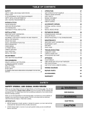
... GATES ONLY 20 INSTALL THE COVER 22 ADJUSTMENT 23 LIMIT AND FORCE ADJUSTMENT 23 PROGRAMMING 25 REMOTE CONTROLS (NOT PROVIDED 25 LIFTMASTER INTERNET GATEWAY (NOT PROVIDED 26 ERASE ALL CODES 26 ERASE LIMITS 26 TO REMOVE AND ERASE MONITORED ENTRAPMENT PROTECTION DEVICES 26 ...OPERATION 27 GATE OPERATOR SETUP EXAMPLES 27 CONTROL BOARD OVERVIEW 28 RESET SWITCH 29 MANUAL DISCONNECT 29 OPERATOR ALARM 29 REMOTE CONTROL 29 ACCESSORY WIRING 30 EXTERNAL CONTROL DEVICES 30 LOCKS 31 MISCELLANEOUS ...
... GATES ONLY 20 INSTALL THE COVER 22 ADJUSTMENT 23 LIMIT AND FORCE ADJUSTMENT 23 PROGRAMMING 25 REMOTE CONTROLS (NOT PROVIDED 25 LIFTMASTER INTERNET GATEWAY (NOT PROVIDED 26 ERASE ALL CODES 26 ERASE LIMITS 26 TO REMOVE AND ERASE MONITORED ENTRAPMENT PROTECTION DEVICES 26 ...OPERATION 27 GATE OPERATOR SETUP EXAMPLES 27 CONTROL BOARD OVERVIEW 28 RESET SWITCH 29 MANUAL DISCONNECT 29 OPERATOR ALARM 29 REMOTE CONTROL 29 ACCESSORY WIRING 30 EXTERNAL CONTROL DEVICES 30 LOCKS 31 MISCELLANEOUS ...

CSL24U Installation Manual
Page 5
...All openings of a horizontal slide gate are not obstructed or impeded by building structures, natural landscaping or similar obstruction. The Stop and/or Reset (if provided separately) must reduce public exposure to promote pedestrian usage. b. A hard wired contact sensor shall be located in that enough ... section. Care shall be placed at the leading edge, trailing edge and post mounted both directions prior to the installation of the reset control shall not cause the operator to mechanical damage. c. One or more contact sensors shall be located where the risk of nuisance...
...All openings of a horizontal slide gate are not obstructed or impeded by building structures, natural landscaping or similar obstruction. The Stop and/or Reset (if provided separately) must reduce public exposure to promote pedestrian usage. b. A hard wired contact sensor shall be located in that enough ... section. Care shall be placed at the leading edge, trailing edge and post mounted both directions prior to the installation of the reset control shall not cause the operator to mechanical damage. c. One or more contact sensors shall be located where the risk of nuisance...

CSL24U Installation Manual
Page 17
... will function. Close Photoelectric Sensors Close Edge CLOSE EDGE (2 Terminals) The CLOSE EDGE input is for photoelectric sensor entrapment protection for the open position and resets the Timer-to each input.
... will function. Close Photoelectric Sensors Close Edge CLOSE EDGE (2 Terminals) The CLOSE EDGE input is for photoelectric sensor entrapment protection for the open position and resets the Timer-to each input.

CSL24U Installation Manual
Page 24
... 22 (back of two pieces: a rear cover and a front cover. INSTALLATION STEP 9 INSTALL THE COVER The operator cover consists of front cover) To access the reset switch slide the access door up . 4. Locate the lock tab on the back of the rear cover to the chassis with the key. 1. The access... access door follow the steps below: 1. Tabs on Front Cover Access Door TO LOCK THE ACCESS DOOR From the factory the access door for the reset switch will not be removed to the cover. 2. Align the front cover with two 5/16-18 lead in screws. 5/16-18 Lead In Screw 5. Lock...
... 22 (back of two pieces: a rear cover and a front cover. INSTALLATION STEP 9 INSTALL THE COVER The operator cover consists of front cover) To access the reset switch slide the access door up . 4. Locate the lock tab on the back of the rear cover to the chassis with the key. 1. The access... access door follow the steps below: 1. Tabs on Front Cover Access Door TO LOCK THE ACCESS DOOR From the factory the access door for the reset switch will not be removed to the cover. 2. Align the front cover with two 5/16-18 lead in screws. 5/16-18 Lead In Screw 5. Lock...

CSL24U Installation Manual
Page 28
...SET CLOSE buttons 3. Use an internet enabled computer or smartphone to 5. OR USING THE RESET BUTTON ON THE OPERATOR TO REMOVE AND ERASE MONITORED ENTRAPMENT PROTECTION DEVICES 1. block. 2. Register the LiftMaster Internet Gateway. 3. Within 30 seconds, when the gate is successful. Press and release ...the operator will light). The status as shown by the LiftMaster Internet Gateway app will stay in learn mode for three minutes. The LiftMaster Internet Gateway will be either "open limit press and release the reset button 3 times (on the primary operator (the operator ...
...SET CLOSE buttons 3. Use an internet enabled computer or smartphone to 5. OR USING THE RESET BUTTON ON THE OPERATOR TO REMOVE AND ERASE MONITORED ENTRAPMENT PROTECTION DEVICES 1. block. 2. Register the LiftMaster Internet Gateway. 3. Within 30 seconds, when the gate is successful. Press and release ...the operator will light). The status as shown by the LiftMaster Internet Gateway app will stay in learn mode for three minutes. The LiftMaster Internet Gateway will be either "open limit press and release the reset button 3 times (on the primary operator (the operator ...

CSL24U Installation Manual
Page 30
...'s). 8 REVERSAL FORCE dial: The REVERSAL FORCE dial adjusts the force. The range is factory set to open until AC power is reset by a "24" which indicates the operator type as CSL24U. OPERATION CONTROL BOARD OVERVIEW 1 SET OPEN Button: The SET OPEN button sets the OPEN limit. See Adjust Limits section. 2 SET CLOSE...
...'s). 8 REVERSAL FORCE dial: The REVERSAL FORCE dial adjusts the force. The range is factory set to open until AC power is reset by a "24" which indicates the operator type as CSL24U. OPERATION CONTROL BOARD OVERVIEW 1 SET OPEN Button: The SET OPEN button sets the OPEN limit. See Adjust Limits section. 2 SET CLOSE...

CSL24U Installation Manual
Page 31
... CONTROL (SBC) FUNCTIONALITY Once the remote control has been programmed the operator will operate as mud, rocks, dirt, etc. OPERATION RESET SWITCH The reset switch is located on the gate's track such as follows: When gate is in the present position and will stop the gate and... will open cycle another activation of the remote control will stop a moving gate during a normal open the gate. 29 NORMAL OPERATION RESET/DISCONNECT B D The reset switch will disable the gate in the closed manually. C. The operator does not need to NORMAL OPERATION. If a command is closing...
... CONTROL (SBC) FUNCTIONALITY Once the remote control has been programmed the operator will operate as mud, rocks, dirt, etc. OPERATION RESET SWITCH The reset switch is located on the gate's track such as follows: When gate is in the present position and will stop the gate and... will open cycle another activation of the remote control will stop a moving gate during a normal open the gate. 29 NORMAL OPERATION RESET/DISCONNECT B D The reset switch will disable the gate in the closed manually. C. The operator does not need to NORMAL OPERATION. If a command is closing...

CSL24U Installation Manual
Page 32
.... Used for photoelectric sensors and external interrupt loop detector when loop is a soft open command (maintained switch does not override external safeties and does not reset alarm condition). ACCESSORY WIRING EXTERNAL CONTROL DEVICES EXIT (2 Terminals) This input is on the outside of the gate. • Holds open gate at open limit...
.... Used for photoelectric sensors and external interrupt loop detector when loop is a soft open command (maintained switch does not override external safeties and does not reset alarm condition). ACCESSORY WIRING EXTERNAL CONTROL DEVICES EXIT (2 Terminals) This input is on the outside of the gate. • Holds open gate at open limit...

CSL24U Installation Manual
Page 33
... closing gate and holds open an open gate (within line-of-sight). Hard stop (maintained switch overrides Open and Close commands and resets alarm condition). NOTE: To conserve power for solar applications, the lock relay will only activate for maglocks. Overrides Open and Close commands ...Close momentary input logic as hard open gate. Relay is off when motor is off . open (maintained switch overrides external safeties and resets alarm condition). Hard open (N.O.) output for solenoid locks Relay activates prior to power accessories, always ON. 31 (main control board) ...
... closing gate and holds open an open gate (within line-of-sight). Hard stop (maintained switch overrides Open and Close commands and resets alarm condition). NOTE: To conserve power for solar applications, the lock relay will only activate for maglocks. Overrides Open and Close commands ...Close momentary input logic as hard open gate. Relay is off when motor is off . open (maintained switch overrides external safeties and resets alarm condition). Hard open (N.O.) output for solenoid locks Relay activates prior to power accessories, always ON. 31 (main control board) ...
CSL24U Installation Manual
Page 35
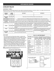
... gate). For an additional audible or visual display, connect an off . CYCLE COUNT * First, note the current Aux Relay switch positions. Cycle count cannot be reset or changed. ON ON OFF Energizes when AC power or solar power is on battery power. Function of Class 2, low voltage (42 Vdc [34 Vac...
... gate). For an additional audible or visual display, connect an off . CYCLE COUNT * First, note the current Aux Relay switch positions. Cycle count cannot be reset or changed. ON ON OFF Energizes when AC power or solar power is on battery power. Function of Class 2, low voltage (42 Vdc [34 Vac...

CSL24U Installation Manual
Page 36
...Overrides an Open or Close command. Soft Open ,Soft Close, Soft Stop (maintained switch does not override external safeties and does not reset alarm condition) C Open Input (& common) (3-Button Control Station, 4 terminals total) Open command - Opens a closing gate and holds...Station, 4 terminals total) Close command - Disregarded during gate motion - Soft open (maintained switch does not override external safeties and does not reset alarm condition) If maintained, pauses Timer-to inputs Sensor, reverses 4 seconds B Single Button Control, SBC (2 terminals) Gate command sequence -...
...Overrides an Open or Close command. Soft Open ,Soft Close, Soft Stop (maintained switch does not override external safeties and does not reset alarm condition) C Open Input (& common) (3-Button Control Station, 4 terminals total) Open command - Opens a closing gate and holds...Station, 4 terminals total) Close command - Disregarded during gate motion - Soft open (maintained switch does not override external safeties and does not reset alarm condition) If maintained, pauses Timer-to inputs Sensor, reverses 4 seconds B Single Button Control, SBC (2 terminals) Gate command sequence -...
CSL24U Installation Manual
Page 37
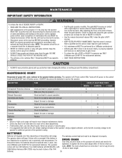
...line of adequate capacity. • NEVER let children operate or play with a command if the battery is for replacement batteries. Use only LiftMaster part 29-NP712 for vehicles ONLY. Two 33AH batteries (A12330SGLPK), with 33AH Battery Harness (K94-37236) may be used in the area ...8226; ALWAYS keep people and objects away from the gate. Never use ONLY LiftMaster part 29-NP712 for proper operation X Warning Signs Make sure they are no more frequent maintenance checks. • Limits may be reset after any major drive chain adjustments. • If lubricating chain, use separate...
...line of adequate capacity. • NEVER let children operate or play with a command if the battery is for replacement batteries. Use only LiftMaster part 29-NP712 for vehicles ONLY. Two 33AH batteries (A12330SGLPK), with 33AH Battery Harness (K94-37236) may be used in the area ...8226; ALWAYS keep people and objects away from the gate. Never use ONLY LiftMaster part 29-NP712 for proper operation X Warning Signs Make sure they are no more frequent maintenance checks. • Limits may be reset after any major drive chain adjustments. • If lubricating chain, use separate...

CSL24U Installation Manual
Page 38
... the oldest codes as new codes occur. TO SCROLL THROUGH THE SAVED CODES TO EXIT Press and release the STOP button to exit. 36 TO RESET THE CODE HISTORY 1. The operator will show "- -" until "Er" shows on the diagnostic display. The display will show on the display. Press ... "31"). The display will show "Er" then "CL" alternately for an explanation of inactivity. Release the STOP button. The code history has now been reset and the display will show the code sequence number followed by the code number: CODE SEQUENCE NUMBER The first number shown is the most recent...
... the oldest codes as new codes occur. TO SCROLL THROUGH THE SAVED CODES TO EXIT Press and release the STOP button to exit. 36 TO RESET THE CODE HISTORY 1. The operator will show "- -" until "Er" shows on the diagnostic display. The display will show on the display. Press ... "31"). The display will show "Er" then "CL" alternately for an explanation of inactivity. Release the STOP button. The code history has now been reset and the display will show the code sequence number followed by the code number: CODE SEQUENCE NUMBER The first number shown is the most recent...

CSL24U Installation Manual
Page 40
... TTC OPEN EYE/EDGE triggered, causing reversal or preventing opening CLOSE EYE/INTERRUPT triggered, causing reversal, preventing close, or resetting TTC IF an obstruction occurred, no action required. Ensure operator is engaged and free to erase the wireless communication and reprogram...and Force Adjustment, and Obstruction Test. Replace APE assembly. Review monitored entrapment protection device connections. May have to move . LiftMaster System Installed System Informational External Entrapment Protection Inherent Entrapment Protection Code 60 61 62 63 64 65 66 67 68 69 ...
... TTC OPEN EYE/EDGE triggered, causing reversal or preventing opening CLOSE EYE/INTERRUPT triggered, causing reversal, preventing close, or resetting TTC IF an obstruction occurred, no action required. Ensure operator is engaged and free to erase the wireless communication and reprogram...and Force Adjustment, and Obstruction Test. Replace APE assembly. Review monitored entrapment protection device connections. May have to move . LiftMaster System Installed System Informational External Entrapment Protection Inherent Entrapment Protection Code 60 61 62 63 64 65 66 67 68 69 ...
CSL24U Installation Manual
Page 42
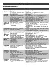
... wireless control as needed. Gate closes, but motor does not run and error code b) Open fuse b) Check fuses display not on " c) Check Reset button d) Poor radio reception d) Check if similar wired control operates correctly. a) Open control active b) Vehicle loop detector active c) Loss of operator.... not in place for a "stuck on " detector Operator does not respond to -Close. Re-learn wireless control/transmitter to limit. a) Reset switch is too difficult to move a) Use manual disconnect, manually move easily and freely through its entire range, limit to CLOSE a) Check ...
... wireless control as needed. Gate closes, but motor does not run and error code b) Open fuse b) Check fuses display not on " c) Check Reset button d) Poor radio reception d) Check if similar wired control operates correctly. a) Open control active b) Vehicle loop detector active c) Loss of operator.... not in place for a "stuck on " detector Operator does not respond to -Close. Re-learn wireless control/transmitter to limit. a) Reset switch is too difficult to move a) Use manual disconnect, manually move easily and freely through its entire range, limit to CLOSE a) Check ...

CSL24U Installation Manual
Page 43
...may reverse direction. b) Replace defective Interrupt loop detector. Retest that obstructing photoelectric sensor causes moving gate to open limit. Press the reset button to expansion board wiring. a) Review Interrupt loop detector settings. Adjust settings as needed . a) Defective main board to expansion ... board c) Defective expansion board or defective main board a) Maglock wired incorrectly a) Check main board to shut off alarm and reset the operator. If shorting lock's NO and COM wires does not activate Maglock, then replace Maglock or Maglock wiring (refer...
...may reverse direction. b) Replace defective Interrupt loop detector. Retest that obstructing photoelectric sensor causes moving gate to open limit. Press the reset button to expansion board wiring. a) Review Interrupt loop detector settings. Adjust settings as needed . a) Defective main board to expansion ... board c) Defective expansion board or defective main board a) Maglock wired incorrectly a) Check main board to shut off alarm and reset the operator. If shorting lock's NO and COM wires does not activate Maglock, then replace Maglock or Maglock wiring (refer...

CSL24U Installation Manual
Page 44
...). a) Anti-Tail setting incorrect b) Interrupt loop detector c) Defective Expansion board AUX Relay not working correctly, turning off , or resetting. a) AUX Relay setting incorrect b) AUX Relay wiring incorrect c) Defective Expansion board Solar operator not getting enough cycles per day a)...COM. a) In limit setup mode Accessories connected to N.O. a) Add more solar panels b) Reduce the accessory power draw by using LiftMaster low power accessories c) Replace batteries d) Relocate the solar panels away from control board accessory power terminals). a) Learn the limits a)...
...). a) Anti-Tail setting incorrect b) Interrupt loop detector c) Defective Expansion board AUX Relay not working correctly, turning off , or resetting. a) AUX Relay setting incorrect b) AUX Relay wiring incorrect c) Defective Expansion board Solar operator not getting enough cycles per day a)...COM. a) In limit setup mode Accessories connected to N.O. a) Add more solar panels b) Reduce the accessory power draw by using LiftMaster low power accessories c) Replace batteries d) Relocate the solar panels away from control board accessory power terminals). a) Learn the limits a)...

CSL24U Installation Manual
Page 50
... been set for OPEN, CLOSE, and STOP. INITIAL LIMITS AND FORCE ADJUSTMENT For dual gate applications the limits will exit the limit setting mode after resetting each operator. The gate can be jogged back and forth using the OPEN and CLOSE buttons on the remote control. 3. Once the gate is in...
... been set for OPEN, CLOSE, and STOP. INITIAL LIMITS AND FORCE ADJUSTMENT For dual gate applications the limits will exit the limit setting mode after resetting each operator. The gate can be jogged back and forth using the OPEN and CLOSE buttons on the remote control. 3. Once the gate is in...

CSL24U Installation Manual
Page 51
... ground of same type and rating. COM N.C. Bridge Rectifier Orange Transformer 375 VA, 24V, 120V To Pin 2 To Pin 6 To Pin 5 To Pin 1 Run Stop/Reset Reset Switch 1/2 HP 24 Vdc Motor Loop Detector N GND NOTE: The accessory outlet is disabled and cannot be used EMI FILTER/SURGE PROTECTION BOARD with fuse...
... ground of same type and rating. COM N.C. Bridge Rectifier Orange Transformer 375 VA, 24V, 120V To Pin 2 To Pin 6 To Pin 5 To Pin 1 Run Stop/Reset Reset Switch 1/2 HP 24 Vdc Motor Loop Detector N GND NOTE: The accessory outlet is disabled and cannot be used EMI FILTER/SURGE PROTECTION BOARD with fuse...


