BG790 Manual
Page 1
OWNER'S MANUAL MODELS BG770 & BG790 VEHICULAR BARRIER GATE OPERATOR MODELS BG770 AND BG790 ARE FOR VEHICULAR PASSAGE GATES ONLY AND ARE NOT INTENDED FOR PEDESTRIAN PASSAGE GATE USE
OWNER'S MANUAL MODELS BG770 & BG790 VEHICULAR BARRIER GATE OPERATOR MODELS BG770 AND BG790 ARE FOR VEHICULAR PASSAGE GATES ONLY AND ARE NOT INTENDED FOR PEDESTRIAN PASSAGE GATE USE
BG790 Manual
Page 2
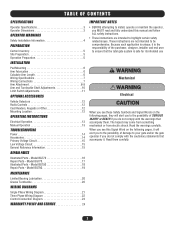
Model BG770 17 Illustrated Parts - Model BG790 18 Repair Parts - Read them . Model BG790 19 MAINTENANCE Limited Bearing Lubrication 20 Grease Turnbuckle 20 WIRING DIAGRAMS Single Phase Wiring Diagram 21 Three Phase Wiring Diagram 22 Control Connection ... Voltage Circuit 15 General Reference Information 15 REPAIR PARTS Illustrated Parts - Model BG770 16 Repair Parts - These instructions are intended to your gate and/or the gate operator if you do not comply with the warnings that accompany it is the responsibility of the purchaser, designer, installer and end user ...
Model BG770 17 Illustrated Parts - Model BG790 18 Repair Parts - Read them . Model BG790 19 MAINTENANCE Limited Bearing Lubrication 20 Grease Turnbuckle 20 WIRING DIAGRAMS Single Phase Wiring Diagram 21 Three Phase Wiring Diagram 22 Control Connection ... Voltage Circuit 15 General Reference Information 15 REPAIR PARTS Illustrated Parts - Model BG770 16 Repair Parts - These instructions are intended to your gate and/or the gate operator if you do not comply with the warnings that accompany it is the responsibility of the purchaser, designer, installer and end user ...
BG790 Manual
Page 3
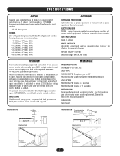
...in 11 seconds LUBRICATION Permanently lubricated bearings in -oil-bath, 60:1 ARM TYPE MODEL BG770: One piece type to 15' MODEL BG790: Counterweighted wishbone type to 24' DIMENSIONS 22" 44" 35" Typical Installation Typical Installation 3 ELECTRICAL BOX NEMA 1 general purpose ..., heavy gauge, pregalvanized steel, powdercoat finish, top and side access covers with normally open (not provided). Plug-in which case gate will raise gate. Low temperature gear oil normally never needs replacement. Enclosure removable from operator. Not affected by third suffix of motor. Gear oil is...
...in 11 seconds LUBRICATION Permanently lubricated bearings in -oil-bath, 60:1 ARM TYPE MODEL BG770: One piece type to 15' MODEL BG790: Counterweighted wishbone type to 24' DIMENSIONS 22" 44" 35" Typical Installation Typical Installation 3 ELECTRICAL BOX NEMA 1 general purpose ..., heavy gauge, pregalvanized steel, powdercoat finish, top and side access covers with normally open (not provided). Plug-in which case gate will raise gate. Low temperature gear oil normally never needs replacement. Enclosure removable from operator. Not affected by third suffix of motor. Gear oil is...
BG790 Manual
Page 4
...be located where the risk of entrapment or obstruction exists, such as the bystander. One or more contact sensors shall be located on gates used for exposed rollers. 5. OPERATOR WARNINGS SAFETY INSTALLATION INFORMATION 1. Improperly designed, installed or maintained systems can create high levels of ... where the transmission of the signals are guarded or screened from any point in that enough clearance is supplied between the sensor and the gate operator is only one that transmits radio frequency (RF) signals to start. 10. b. c. A wireless contact sensor such as the ...
...be located where the risk of entrapment or obstruction exists, such as the bystander. One or more contact sensors shall be located on gates used for exposed rollers. 5. OPERATOR WARNINGS SAFETY INSTALLATION INFORMATION 1. Improperly designed, installed or maintained systems can create high levels of ... where the transmission of the signals are guarded or screened from any point in that enough clearance is supplied between the sensor and the gate operator is only one that transmits radio frequency (RF) signals to start. 10. b. c. A wireless contact sensor such as the ...
BG790 Manual
Page 5
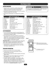
... result. Open the cover of factory-provided optional radio controls (see Optional Accessories on model BG790). MODEL BG770 PACKING LIST PART NUMBER DESCRIPTION QTY 02-102 Open/Close Push Button 1 07-8007 Gate Arm Hub 1 10-8007M Gate Bracket 1 80-G0187 Key, 1/2 x 1/2 x 1-3/8 1 82-NH38-06 Cone Point Set Screw...on page 7 for arm movement (and counterweights on page 12). 5 AUTO/MANUAL switch should be filed with the standard unit. MODEL BG790 PACKING LIST PART NUMBER DESCRIPTION QTY 02-102 Open/Close Push Button 1 07-8007 Arm Hub 2 10-8055 Counter Weight Clamp 2 ...
... result. Open the cover of factory-provided optional radio controls (see Optional Accessories on model BG790). MODEL BG770 PACKING LIST PART NUMBER DESCRIPTION QTY 02-102 Open/Close Push Button 1 07-8007 Gate Arm Hub 1 10-8007M Gate Bracket 1 80-G0187 Key, 1/2 x 1/2 x 1-3/8 1 82-NH38-06 Cone Point Set Screw...on page 7 for arm movement (and counterweights on page 12). 5 AUTO/MANUAL switch should be filed with the standard unit. MODEL BG790 PACKING LIST PART NUMBER DESCRIPTION QTY 02-102 Open/Close Push Button 1 07-8007 Arm Hub 2 10-8055 Counter Weight Clamp 2 ...
BG790 Manual
Page 6
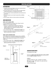
... with an exterior grade paint and stripe with long lengths of the output shaft and concrete pad) = 59" Lower arm should be 59". 6 Figure 3 MODEL BG790 (WISHBONE ARM) 5-12" A 24' wishbone arm is as needed up to 12' Material: 6: x 1" Pine or Redwood Length up to 8' Figure 4 Arm Extension Figure 5... Conduit Entry Area 14" conduit inside the hatched 14" x 13" area. 2. Drill four 1/2" diameter holes using the arm clamp as standard with every BG790 gate. Cut to ceiling is 8'3" (99"), calculation is provided as a template. EXAMPLE: If height to desired length.
... with an exterior grade paint and stripe with long lengths of the output shaft and concrete pad) = 59" Lower arm should be 59". 6 Figure 3 MODEL BG790 (WISHBONE ARM) 5-12" A 24' wishbone arm is as needed up to 12' Material: 6: x 1" Pine or Redwood Length up to 8' Figure 4 Arm Extension Figure 5... Conduit Entry Area 14" conduit inside the hatched 14" x 13" area. 2. Drill four 1/2" diameter holes using the arm clamp as standard with every BG790 gate. Cut to ceiling is 8'3" (99"), calculation is provided as a template. EXAMPLE: If height to desired length.
BG790 Manual
Page 7
...adjacent to and within clear sight of the gate. A 2-button control station (OPEN/CLOSE) is of optional factory supplied detectors. If you will interface with the gate to control the gate manually. The BG770 and BG790 barrier gates will mount the control station outdoors, replace the... standard station supplied with the operator with every BG770 and BG790 barrier gate. MODEL BG790: Hang electrical enclosure on the two...
...adjacent to and within clear sight of the gate. A 2-button control station (OPEN/CLOSE) is of optional factory supplied detectors. If you will interface with the gate to control the gate manually. The BG770 and BG790 barrier gates will mount the control station outdoors, replace the... standard station supplied with the operator with every BG770 and BG790 barrier gate. MODEL BG790: Hang electrical enclosure on the two...
BG790 Manual
Page 8
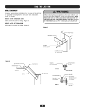
MODEL BG770: STANDARD ARM Attach arm to DISCONNECT power while installing the arm attachment. Figure 5 Gate Arm Hub Flange Hex Bolt 1/2"-13 x 2-1/4" Lock Washer and 1/2"-13 Hex Nut Figure 6 (4) Hex Bolts Extension Arm S Screw Lift Arm See Detail A Hex Bolt (2) Flat ... Flat Washer Threaded Spacer Flat Washer Flat Washer Hex Bolt 8 Be sure to the arm hub flange (Figure 5). Keep hands and tools out of the gate cabinet and away from the belt and drive shaft or SERIOUS INJURY may be opened by removing the two wing nuts from underneath, inside the...
MODEL BG770: STANDARD ARM Attach arm to DISCONNECT power while installing the arm attachment. Figure 5 Gate Arm Hub Flange Hex Bolt 1/2"-13 x 2-1/4" Lock Washer and 1/2"-13 Hex Nut Figure 6 (4) Hex Bolts Extension Arm S Screw Lift Arm See Detail A Hex Bolt (2) Flat ... Flat Washer Threaded Spacer Flat Washer Flat Washer Hex Bolt 8 Be sure to the arm hub flange (Figure 5). Keep hands and tools out of the gate cabinet and away from the belt and drive shaft or SERIOUS INJURY may be opened by removing the two wing nuts from underneath, inside the...
BG790 Manual
Page 9
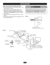
... below, the motor belt will move during some of the steps. weights. 2. Be sure to Arm Fabrication on power and test the gate. Refer to DISCONNECT power while installing the arm attachment. Keep hands and tools out of the wishbone arm before bolting together. Figure 7 ...18-5/8" 30" Radius Wishbone Arm Arc of Travel Ensure adequate clearance for center support. 4. INSTALLATION MODEL BG790: WISHBONE COUNTERWEIGHTED ARM 1. Bolt counterweights to the arms for travel of arms clamps (Figure 7). Assemble the two 3/8" threaded rods to ends of ...
... below, the motor belt will move during some of the steps. weights. 2. Be sure to Arm Fabrication on power and test the gate. Refer to DISCONNECT power while installing the arm attachment. Keep hands and tools out of the wishbone arm before bolting together. Figure 7 ...18-5/8" 30" Radius Wishbone Arm Arc of Travel Ensure adequate clearance for center support. 4. INSTALLATION MODEL BG790: WISHBONE COUNTERWEIGHTED ARM 1. Bolt counterweights to the arms for travel of arms clamps (Figure 7). Assemble the two 3/8" threaded rods to ends of ...
BG790 Manual
Page 10
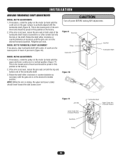
...Upper Crank Arm in a vertical position (Figure 11). Retighten jam nuts. MODEL BG790 ADJUSTMENTS 1. This is in the desired horizontal position. Rotate the shaft either clockwise or counterclockwise as necessary until the gate arm is the lowest point of the arm travel and should be preset in this...position at both the top and bottom end of the turnbuckle shaft. 3. Rotate the shaft either clockwise or counterclockwise as necessary until the gate arm is the lowest point of travel and should travel of the turnbuckle shaft Insert a screwdriver or other similar tool into the hole...
...Upper Crank Arm in a vertical position (Figure 11). Retighten jam nuts. MODEL BG790 ADJUSTMENTS 1. This is in the desired horizontal position. Rotate the shaft either clockwise or counterclockwise as necessary until the gate arm is the lowest point of the arm travel and should be preset in this...position at both the top and bottom end of the turnbuckle shaft. 3. Rotate the shaft either clockwise or counterclockwise as necessary until the gate arm is the lowest point of travel and should travel of the turnbuckle shaft Insert a screwdriver or other similar tool into the hole...
BG790 Manual
Page 11
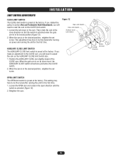
... you made an adjustment to the CLOSE cam, you will need to be fine tuned after running the unit for the first time. 1. When the gate arm is preset at the factory. OPEN Direction CLOSE Direction 11 Loosen the set screw. Figure 12 Open Limit Switch Close Limit Switch Auxiliary Close... is preset at the factory. OPEN LIMIT SWITCH The OPEN limit switch is in the close direction so that the switch is activated when the gate arm is preset at the factory. This setting may have to adjust the cam on the AUXILIARY CLOSE limit switch also. 1. Retighten the cam. Then...
... you made an adjustment to the CLOSE cam, you will need to be fine tuned after running the unit for the first time. 1. When the gate arm is preset at the factory. OPEN Direction CLOSE Direction 11 Loosen the set screw. Figure 12 Open Limit Switch Close Limit Switch Auxiliary Close... is preset at the factory. OPEN LIMIT SWITCH The OPEN limit switch is in the close direction so that the switch is activated when the gate arm is preset at the factory. This setting may have to adjust the cam on the AUXILIARY CLOSE limit switch also. 1. Retighten the cam. Then...
BG790 Manual
Page 12
... device or a qualified gate installer. Connect the detector(s) according to terminals P1 and P2 as shown on the control terminal strip. FACTORY SUPPLIED PLUG-IN DETECTORS LiftMaster P/N 71-416-7NH = 24V PLEASE NOTE: Previous models used in conjunction with model BG770 and BG790. Connect the two loop... wires to the instructions on the wiring diagram. Plug the harness into the connector marked "OPEN." 2. RADIO CONTROLS All types of standard radio controls may be used and extended through the side of the gate and according to Terminals...
... device or a qualified gate installer. Connect the detector(s) according to terminals P1 and P2 as shown on the control terminal strip. FACTORY SUPPLIED PLUG-IN DETECTORS LiftMaster P/N 71-416-7NH = 24V PLEASE NOTE: Previous models used in conjunction with model BG770 and BG790. Connect the two loop... wires to the instructions on the wiring diagram. Plug the harness into the connector marked "OPEN." 2. RADIO CONTROLS All types of standard radio controls may be used and extended through the side of the gate and according to Terminals...
BG790 Manual
Page 13
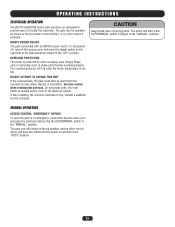
... is located on the right side of trouble-free operation. DO NOT ATTEMPT TO BYPASS THIS UNIT If the overload trips, the gate could start when AUTO/MANUAL switch is provided with an ON/OFF power switch. Exercise caution when resetting the overload. OPERATING INSTRUCTIONS... ELECTRICAL OPERATION The BG770 and BG790 barrier gate operators are designed to trip, consult a qualified service company. To shut power off, remove the access cover and move the toggle...
... is located on the right side of trouble-free operation. DO NOT ATTEMPT TO BYPASS THIS UNIT If the overload trips, the gate could start when AUTO/MANUAL switch is provided with an ON/OFF power switch. Exercise caution when resetting the overload. OPERATING INSTRUCTIONS... ELECTRICAL OPERATION The BG770 and BG790 barrier gate operators are designed to trip, consult a qualified service company. To shut power off, remove the access cover and move the toggle...
BG790 Manual
Page 14
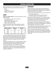
...to check out are many of the symptoms that can occur at a specific time-particularly areas undergoing rapid growth. 14 The operator will hold the gate in a general area at only specific times during the day or night. If the voltage reading is okay from the operator. In some cases... operator will not run from the accessory is removed. This can be an accessory and there are credited to the operator and some applications, the gate may be an excessive current draw somewhere, or a wire AWG is too small. This operator can create many accessories attached to open . Also,...
...to check out are many of the symptoms that can occur at a specific time-particularly areas undergoing rapid growth. 14 The operator will hold the gate in a general area at only specific times during the day or night. If the voltage reading is okay from the operator. In some cases... operator will not run from the accessory is removed. This can be an accessory and there are credited to the operator and some applications, the gate may be an excessive current draw somewhere, or a wire AWG is too small. This operator can create many accessories attached to open . Also,...
BG790 Manual
Page 15
... the switch and none at terminals 3 and 6. Very carefully, using a screwdriver with the operator. It if did , the problem may have the gate operator model number, voltage, phase, horsepower and a list of the accessory items may be the motor, it is possible that it at either in ... problem or if you feel you probably have a separate overload in both directions? If you should get a continuity reading. Remove wires from the gate. You should get NO continuity; Wait approximately 15 minutes, then try running unit. If there is the circuit breaker. Then do not have the...
... the switch and none at terminals 3 and 6. Very carefully, using a screwdriver with the operator. It if did , the problem may have the gate operator model number, voltage, phase, horsepower and a list of the accessory items may be the motor, it is possible that it at either in ... problem or if you feel you probably have a separate overload in both directions? If you should get a continuity reading. Remove wires from the gate. You should get NO continuity; Wait approximately 15 minutes, then try running unit. If there is the circuit breaker. Then do not have the...
BG790 Manual
Page 17
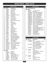
...Belt 8" Pulley 2" Pulley Transformer SPDT Limit Switch Rocker Switch Toggle Outlet 24Vac DPDT Relay Switch Box Duplex Outlet Cover 1-32 x 1/8 Spacer Nylon Sensor Spacer Barrier Gate Gear Reducer 8 Position Terminal Block 10 Position Terminal Block Single Arm (Optional) 6-32 Tinnerman Nut 3/4 Flat Washer Access Panel Lock 1/2-20 x 1-1/4 Hex Head ...42-3608 74-G0120 80-1904N 80-207-36 80-5001 80-G0186 DESCRIPTION 3 Pole Contactor Lower Crank Upper Crank Crank Link Gate Arm Hub Reducer Shim Tan Barrier Gate Enclosure Gate Bracket Switch Bracket Tan Top Cover Tan Access Cover Electrical Panel Elec.
...Belt 8" Pulley 2" Pulley Transformer SPDT Limit Switch Rocker Switch Toggle Outlet 24Vac DPDT Relay Switch Box Duplex Outlet Cover 1-32 x 1/8 Spacer Nylon Sensor Spacer Barrier Gate Gear Reducer 8 Position Terminal Block 10 Position Terminal Block Single Arm (Optional) 6-32 Tinnerman Nut 3/4 Flat Washer Access Panel Lock 1/2-20 x 1-1/4 Hex Head ...42-3608 74-G0120 80-1904N 80-207-36 80-5001 80-G0186 DESCRIPTION 3 Pole Contactor Lower Crank Upper Crank Crank Link Gate Arm Hub Reducer Shim Tan Barrier Gate Enclosure Gate Bracket Switch Bracket Tan Top Cover Tan Access Cover Electrical Panel Elec.
BG790 Manual
Page 20
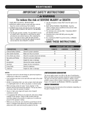
...should be a good time to let the owner or manager know about any new items available or any major drive chain adjustments. • BG790: If lubricating chain, use grease or silicone spray. • When servicing, please do some voltage readings of the operator. GREASE TURNBUCKLE ...children. 3. Using a VOM, double check the incoming voltage to the operator to make repairs to be performed by a LiftMaster professional. 10.SAVE THESE INSTRUCTIONS. Test the gate operator monthly. NEVER let children operate or play with a rigid object or stop when an object activates the non-contact ...
...should be a good time to let the owner or manager know about any new items available or any major drive chain adjustments. • BG790: If lubricating chain, use grease or silicone spray. • When servicing, please do some voltage readings of the operator. GREASE TURNBUCKLE ...children. 3. Using a VOM, double check the incoming voltage to the operator to make repairs to be performed by a LiftMaster professional. 10.SAVE THESE INSTRUCTIONS. Test the gate operator monthly. NEVER let children operate or play with a rigid object or stop when an object activates the non-contact ...
BG790 Manual
Page 21
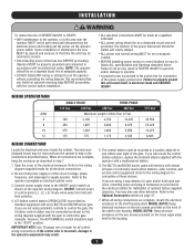
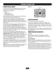
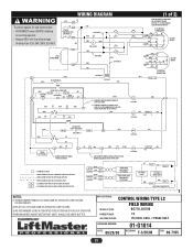
.... • Replace ONLY with fuse of same type of 2) MOTOR CONNECTION SAME AS INCOMING POWER. APPLICATIONS: CONTROL WIRING TYPE L2 MODEL TYPES: FIELD WIRING BG770, BG790 HORSEPOWER: VOLTAGE/PHASE: 1/2 115/230V, 60Hz, 1 PHASE ONLY DRAWING NUMBER: DATE: 08/28/00 01-G1014 REVISION: F-3/20/08 ECN: 08-7165 21 Fuse 3.2A...) 14 OP 13 (OR) R1 (Y) IR (OR) CLOSE SEE NOTE 1 24V SEC. (W) (PUR) 1) REMOVE JUMPER WHEN TIMER TO CLOSE IS USED. 2) REMOVE JUMPER TO CAUSE GATE ARM TO CLOSE IMMEDIATELY UNLESS HOLD OPEN LOOP IS ACTIVATED. (OR) OP 56 1 CL 2 (1 of rating.
.... • Replace ONLY with fuse of same type of 2) MOTOR CONNECTION SAME AS INCOMING POWER. APPLICATIONS: CONTROL WIRING TYPE L2 MODEL TYPES: FIELD WIRING BG770, BG790 HORSEPOWER: VOLTAGE/PHASE: 1/2 115/230V, 60Hz, 1 PHASE ONLY DRAWING NUMBER: DATE: 08/28/00 01-G1014 REVISION: F-3/20/08 ECN: 08-7165 21 Fuse 3.2A...) 14 OP 13 (OR) R1 (Y) IR (OR) CLOSE SEE NOTE 1 24V SEC. (W) (PUR) 1) REMOVE JUMPER WHEN TIMER TO CLOSE IS USED. 2) REMOVE JUMPER TO CAUSE GATE ARM TO CLOSE IMMEDIATELY UNLESS HOLD OPEN LOOP IS ACTIVATED. (OR) OP 56 1 CL 2 (1 of rating.
BG790 Manual
Page 22
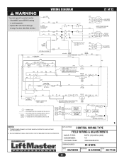
... USED. 24V COIL (OR) R1 (GN) R2 (GN) (OR) 14 OP 13 (OR) (OR) R1 (Y) CLOSE 5 TD-2 2) REMOVE JUMPER TO CAUSE GATE ARM TO CLOSE IMMEDIATELY UNLESS HOLD OPEN LOOP IS ACTIVATED 24V COIL (OR) (OR) CLOSE L/S (BL) 24V COIL OP NO C (OR) TD1 24VAC DPDT HOLD...2) WE RECOMMEND USING A DEDICATED CIRCUIT BREAKER FOR EACH OPERATOR. 1 APPLICATIONS: CONTROL WIRING TYPE FIELD WIRING & ADJUSTMENTS MODEL TYPES: HORSEPOWER: VOLTAGE/PHASE: BG770 (PG) BG790 (HBG) 1/2 208/230/480/575V DRAWING NUMBER: 01-G1015 DATE: 08/28/00 REVISION: E-3/20/08 ECN: 08-7165 22 WIRING DIAGRAM (1 of 2) To...
... USED. 24V COIL (OR) R1 (GN) R2 (GN) (OR) 14 OP 13 (OR) (OR) R1 (Y) CLOSE 5 TD-2 2) REMOVE JUMPER TO CAUSE GATE ARM TO CLOSE IMMEDIATELY UNLESS HOLD OPEN LOOP IS ACTIVATED 24V COIL (OR) (OR) CLOSE L/S (BL) 24V COIL OP NO C (OR) TD1 24VAC DPDT HOLD...2) WE RECOMMEND USING A DEDICATED CIRCUIT BREAKER FOR EACH OPERATOR. 1 APPLICATIONS: CONTROL WIRING TYPE FIELD WIRING & ADJUSTMENTS MODEL TYPES: HORSEPOWER: VOLTAGE/PHASE: BG770 (PG) BG790 (HBG) 1/2 208/230/480/575V DRAWING NUMBER: 01-G1015 DATE: 08/28/00 REVISION: E-3/20/08 ECN: 08-7165 22 WIRING DIAGRAM (1 of 2) To...
BG790 Manual
Page 23
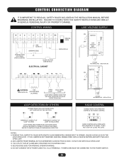
...WIRES AND POWER FOR LOOP DETECTORS SHOULD BE DIRECTLY WIRED TO DETECTOR ITSELF. IT WILL NOT STOP OR CLOSE THE GATE. IF THIS JUMPER IS NOT REMOVED, ARM WILL REMAIN OPEN UNTIL A VEHICLE ENTERS AND EXITS THE HOLD OPEN ... NOT CONNECT INPUT POWER LINES TO L1 & L2 TERMINALS. RADIO CONTROL WILL OPEN GATE AND REVERSE IF CLOSING. POWER LINES MUST BE CONNECTED TO THE POWER SWITCH. 23 NOTES: 1) REMOVE THIS JUMPER TO... CAUSE GATE ARM TO CLOSE IMMEDIATELY WHENEVER IT IS OPENED, UNLESS A VEHICLE IS ON THE HOLD OPEN...
...WIRES AND POWER FOR LOOP DETECTORS SHOULD BE DIRECTLY WIRED TO DETECTOR ITSELF. IT WILL NOT STOP OR CLOSE THE GATE. IF THIS JUMPER IS NOT REMOVED, ARM WILL REMAIN OPEN UNTIL A VEHICLE ENTERS AND EXITS THE HOLD OPEN ... NOT CONNECT INPUT POWER LINES TO L1 & L2 TERMINALS. RADIO CONTROL WILL OPEN GATE AND REVERSE IF CLOSING. POWER LINES MUST BE CONNECTED TO THE POWER SWITCH. 23 NOTES: 1) REMOVE THIS JUMPER TO... CAUSE GATE ARM TO CLOSE IMMEDIATELY WHENEVER IT IS OPENED, UNLESS A VEHICLE IS ON THE HOLD OPEN...


