
APT LOGIC 3 Manual
Page 1
... station will signal when the set an internal Maintenance Cycle Counter. An LED on Board 315MHz NOT FOR RESIDENTIAL USE L 3 ogic OWNER'S MANUAL APT INDUSTRIAL DUTY COMMERCIAL DOOR OPERATOR This Operator Features the Enhanced INTENAN MA E M E C AL 2 YEAR WARRANTY Serial # Box Installation Date E PATENT PENDING R T T SYS The Maintenance Alert System™ allows the...
... station will signal when the set an internal Maintenance Cycle Counter. An LED on Board 315MHz NOT FOR RESIDENTIAL USE L 3 ogic OWNER'S MANUAL APT INDUSTRIAL DUTY COMMERCIAL DOOR OPERATOR This Operator Features the Enhanced INTENAN MA E M E C AL 2 YEAR WARRANTY Serial # Box Installation Date E PATENT PENDING R T T SYS The Maintenance Alert System™ allows the...
APT LOGIC 3 Manual
Page 2
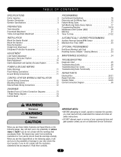
...Troubleshooting Guide 26 Troubleshooting Error Codes 27 Troubleshooting Radio Functionality 28 REPAIR PARTS Electrical Box 30-31 Repair Parts Kits 32-33 Operator Notes 34-35 Control Connection Diagram 36 WARNING Mechanical WCAARUNTIIONNG Electrical CWAAURTNIOINNG WARNING IMPORTANT NOTES: WWAARRNNIINNGG • BEFORE attempting to ... this Signal Word on the following pages, they will alert you to the possibility of your door and/or the door operator if you are an Authorized Service Technician. Read the warnings carefully. When you see these Safety Symbols and Signal Words on...
...Troubleshooting Guide 26 Troubleshooting Error Codes 27 Troubleshooting Radio Functionality 28 REPAIR PARTS Electrical Box 30-31 Repair Parts Kits 32-33 Operator Notes 34-35 Control Connection Diagram 36 WARNING Mechanical WCAARUNTIIONNG Electrical CWAAURTNIOINNG WARNING IMPORTANT NOTES: WWAARRNNIINNGG • BEFORE attempting to ... this Signal Word on the following pages, they will alert you to the possibility of your door and/or the door operator if you are an Authorized Service Technician. Read the warnings carefully. When you see these Safety Symbols and Signal Words on...

APT LOGIC 3 Manual
Page 3
OPERATOR DIMENSIONS WEIGHTS AND DIMENSIONS HANGING WEIGHT: 80-110 LBS. (36.3-50 kg) 4" (104.2" cm) 131.035-1"/8(3"3.15 cm) * Do*DoroHoreHigehitgPhltuPslu4sfe4efte(emti(n1im.2u2mm)) (minimum) Highest ...
OPERATOR DIMENSIONS WEIGHTS AND DIMENSIONS HANGING WEIGHT: 80-110 LBS. (36.3-50 kg) 4" (104.2" cm) 131.035-1"/8(3"3.15 cm) * Do*DoroHoreHigehitgPhltuPslu4sfe4efte(emti(n1im.2u2mm)) (minimum) Highest ...

APT LOGIC 3 Manual
Page 4
... OUTPUT SHAFT SPEED 96 R.P.M. See pages 16 and 17 for emergency manual door operation. Secondary: #41 chain/sprocket. SAFETY DISCONNECT Quick disconnect door arm for optional wiring types and operating modes. SAFETY PHOTO EYES (Optional CPS-L): Through beam or retro reflective devices used...Button Station. SAFETY EDGE (Optional): Electric or pneumatic sensing device attached to open and close with open override. OPERATOR SPECIFICATIONS MOTOR TYPE Continuous Duty HORSEPOWER 1/2 HP SPEED 1725 RPM VOLTAGE 115 Volts - MECHANICAL DRIVE REDUCTION Primary: Heavy duty (5L) ...
... OUTPUT SHAFT SPEED 96 R.P.M. See pages 16 and 17 for emergency manual door operation. Secondary: #41 chain/sprocket. SAFETY DISCONNECT Quick disconnect door arm for optional wiring types and operating modes. SAFETY PHOTO EYES (Optional CPS-L): Through beam or retro reflective devices used...Button Station. SAFETY EDGE (Optional): Electric or pneumatic sensing device attached to open and close with open override. OPERATOR SPECIFICATIONS MOTOR TYPE Continuous Duty HORSEPOWER 1/2 HP SPEED 1725 RPM VOLTAGE 115 Volts - MECHANICAL DRIVE REDUCTION Primary: Heavy duty (5L) ...
APT LOGIC 3 Manual
Page 5
... functional, install an interlock switch. • ALWAYS call a trained professional door serviceman if door binds, sticks or is out of operator is loose before removing links. Pull the release clip on the frame of the powerhead so that the motor side of balance. Using...under extreme tension and can cause SERIOUS PERSONAL INJURY. • Disable ALL locks and remove ALL ropes connected to door BEFORE installing and operating door operator to achieve proper adjustment. 3. Pull it towards door). If necessary, remove links from door ). 2. Using the 3/8"-16 x 3/4"...
... functional, install an interlock switch. • ALWAYS call a trained professional door serviceman if door binds, sticks or is out of operator is loose before removing links. Pull the release clip on the frame of the powerhead so that the motor side of balance. Using...under extreme tension and can cause SERIOUS PERSONAL INJURY. • Disable ALL locks and remove ALL ropes connected to door BEFORE installing and operating door operator to achieve proper adjustment. 3. Pull it towards door). If necessary, remove links from door ). 2. Using the 3/8"-16 x 3/4"...
APT LOGIC 3 Manual
Page 6
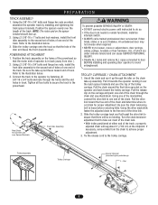
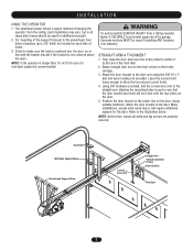
... has been properly aligned and is working smoothly. Close the door and mark the inside vertical centerline of Door Header Bracket Drill Pattern Operator Alignment 6 Extend the line onto the header wall above the high point. Align the bracket holes and join with suitable mounting brackets ... illustration below. MOUNT THE HEADER BRACKET 1. Refer to the preparation on the header wall 4" (10.2 cm) above the door. Raise the operator to the highest point of travel clearance for location, mount a suitable wood block or length of the door center only if a torsion spring or...
... has been properly aligned and is working smoothly. Close the door and mark the inside vertical centerline of Door Header Bracket Drill Pattern Operator Alignment 6 Extend the line onto the header wall above the high point. Align the bracket holes and join with suitable mounting brackets ... illustration below. MOUNT THE HEADER BRACKET 1. Refer to the preparation on the header wall 4" (10.2 cm) above the door. Raise the operator to the highest point of travel clearance for location, mount a suitable wood block or length of the door center only if a torsion spring or...
APT LOGIC 3 Manual
Page 7
NOTE: If the operator is longer than 15' (4.57 m) use of a mid-span support is centered over the door (or in line with the top rollers... Roller Mid-Span Support Brace Powerhead Support Brace Curved Door Arm Straight Arm Vertical Centerline of the garage. For mounting of hanging the operator from a falling operator, CAUTION fasten it SECURELY to 3/8" bolts) are properly secured. Check to the straight arm, aligning the mounting holes in line with... the two pieces to the door arm using the 3/8"-16 x 1" bolt and nylon locking nut provided. I N S TA L L AT I O N HANG THE OPERATOR 1.
NOTE: If the operator is longer than 15' (4.57 m) use of a mid-span support is centered over the door (or in line with the top rollers... Roller Mid-Span Support Brace Powerhead Support Brace Curved Door Arm Straight Arm Vertical Centerline of the garage. For mounting of hanging the operator from a falling operator, CAUTION fasten it SECURELY to 3/8" bolts) are properly secured. Check to the straight arm, aligning the mounting holes in line with... the two pieces to the door arm using the 3/8"-16 x 1" bolt and nylon locking nut provided. I N S TA L L AT I O N HANG THE OPERATOR 1.

APT LOGIC 3 Manual
Page 8
...30.48 cm) above the top of the door. Repeat steps 1 and 2 for door industry type operators with an isolated normally open (N.O.) dry contact output are compatible with your operator. SAFETY (Aux. WARNING To reduce the risk of SEVERE INJURY or DEATH, ALWAYS CAUTION install reversing ... the sensing edge on safety devices, please contact your sensing device to the operator, refer to operator. COIL CORD Connect operator end of coil cord to junction box (not provided) fastened to the operator electrical box in accordance with local codes. See field connection terminals identified as ...
...30.48 cm) above the top of the door. Repeat steps 1 and 2 for door industry type operators with an isolated normally open (N.O.) dry contact output are compatible with your operator. SAFETY (Aux. WARNING To reduce the risk of SEVERE INJURY or DEATH, ALWAYS CAUTION install reversing ... the sensing edge on safety devices, please contact your sensing device to the operator, refer to operator. COIL CORD Connect operator end of coil cord to junction box (not provided) fastened to the operator electrical box in accordance with local codes. See field connection terminals identified as ...
APT LOGIC 3 Manual
Page 9
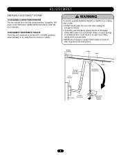
... TROLLEY The trolley will reconnect on the emergency release handle and raise or lower the door manually. ADJUSTMENT EMERGENCY DISCONNECT SYSTEM TO DISCONNECT DOOR FROM OPERATOR The door should be in an open door falling rapidly and/or unexpectedly. • NEVER use emergency release handle to disengage trolley ONLY when door... arm when pulling the emergency release. • If possible, use emergency release handle unless doorway is CLOSED. Pull down on the next UP or DOWN operation, either manually or by using the door control or remote.
... TROLLEY The trolley will reconnect on the emergency release handle and raise or lower the door manually. ADJUSTMENT EMERGENCY DISCONNECT SYSTEM TO DISCONNECT DOOR FROM OPERATOR The door should be in an open door falling rapidly and/or unexpectedly. • NEVER use emergency release handle to disengage trolley ONLY when door... arm when pulling the emergency release. • If possible, use emergency release handle unless doorway is CLOSED. Pull down on the next UP or DOWN operation, either manually or by using the door control or remote.

APT LOGIC 3 Manual
Page 10
... Nut Spring Clutch Pad Clutch Plate Cotterpin Washer Clutch Pulley 10 Replace brake assembly when necessary. It is designed to protect the door and motorized operator. Refer to the illustration for the life of the brake assembly. Back off clutch nut until there is just enough tension to permit the... operator to move the door smoothly but to allow the clutch to slip if the door is met and causes the clutch to slip, the Auxiliary ...
... Nut Spring Clutch Pad Clutch Plate Cotterpin Washer Clutch Pulley 10 Replace brake assembly when necessary. It is designed to protect the door and motorized operator. Refer to the illustration for the life of the brake assembly. Back off clutch nut until there is just enough tension to permit the... operator to move the door smoothly but to allow the clutch to slip if the door is met and causes the clutch to slip, the Auxiliary ...

APT LOGIC 3 Manual
Page 11
...individual. • DO NOT install ANY wiring or attempt to run in the electrical box enclosure marked with local electrical codes. 2. The operator should be on a dedicated circuit and well protected. We recommend that time the unit may be returned to service. • Disconnect ... as the power wiring. IMPORTANT NOTE: This unit must be properly grounded. Connect earth ground to the chassis ground screw in the area near the operator MUST NOT be properly grounded and connected in electric shock and serious injury. NING P O W E R W I R I N GWA& RGNRINO GU N D W I R I N G ...
...individual. • DO NOT install ANY wiring or attempt to run in the electrical box enclosure marked with local electrical codes. 2. The operator should be on a dedicated circuit and well protected. We recommend that time the unit may be returned to service. • Disconnect ... as the power wiring. IMPORTANT NOTE: This unit must be properly grounded. Connect earth ground to the chassis ground screw in the area near the operator MUST NOT be properly grounded and connected in electric shock and serious injury. NING P O W E R W I R I N GWA& RGNRINO GU N D W I R I N G ...
APT LOGIC 3 Manual
Page 12
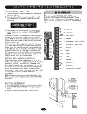
... 24 VOLT AC 24V AC 13 24 VOLT AC TIMER DEFEAT 12 TIMER DEFEAT CMN 11 COMMON MAS 10 MAINTENANCE ALERT SYSTEM EYES 9 PHOTO EYES (LiftMaster Only) EDGE 8 REVERSE OPEN 7 OPEN CLOSE 6 CLOSE STOP 5 STOP CMN 4 COMMON 3 INTERLOCK 2 INTERLOCK SBC 1 SINGLE BUTTON CONTROL MOUNTING INSTRUCTIONS 1. ... wires through the conduit hole in receiver, remove or disconnect the coaxial cable from the radio remote. In TS control wiring the operator will change the motor rotation as well as shown. 2. Control Station 4' Approximate Optional Controls Maintenance Alert SystemTM If light is Flashing...
... 24 VOLT AC 24V AC 13 24 VOLT AC TIMER DEFEAT 12 TIMER DEFEAT CMN 11 COMMON MAS 10 MAINTENANCE ALERT SYSTEM EYES 9 PHOTO EYES (LiftMaster Only) EDGE 8 REVERSE OPEN 7 OPEN CLOSE 6 CLOSE STOP 5 STOP CMN 4 COMMON 3 INTERLOCK 2 INTERLOCK SBC 1 SINGLE BUTTON CONTROL MOUNTING INSTRUCTIONS 1. ... wires through the conduit hole in receiver, remove or disconnect the coaxial cable from the radio remote. In TS control wiring the operator will change the motor rotation as well as shown. 2. Control Station 4' Approximate Optional Controls Maintenance Alert SystemTM If light is Flashing...

APT LOGIC 3 Manual
Page 16
... limits. SELECTOR DIAL FAILSAFE SWITCH DETERMINE AND SET WIRING TYPE Read the descriptions of close , open and stop control or a jumper must also set the operators open and close with constant pressure to close button will light up. SET THE SELECTOR DIAL TO THE DESIRED WIRING MODE: NOTE: For failsafe wiring...
... limits. SELECTOR DIAL FAILSAFE SWITCH DETERMINE AND SET WIRING TYPE Read the descriptions of close , open and stop control or a jumper must also set the operators open and close with constant pressure to close button will light up. SET THE SELECTOR DIAL TO THE DESIRED WIRING MODE: NOTE: For failsafe wiring...

APT LOGIC 3 Manual
Page 17
..., loop detector, pneumatic or electrical treadles, radio controls, one button stations, pull cords, etc. 3. Open override means that causes door to operate.) FSTS Momentary button contact for open limit bypassing the mid stop with 3-Button Station, 1-Button Station, 1 & 3 Button Remote Control. (NOTE...photo eyes to open , except a reversing device, activates the Timer To Close. Self Monitoring safety device must be installed to operate this wiring type. See Self Monitoring Safety Device Options. E2 Failsafe Same functions as B2. See Self Monitoring Safety Device Options....
..., loop detector, pneumatic or electrical treadles, radio controls, one button stations, pull cords, etc. 3. Open override means that causes door to operate.) FSTS Momentary button contact for open limit bypassing the mid stop with 3-Button Station, 1-Button Station, 1 & 3 Button Remote Control. (NOTE...photo eyes to open , except a reversing device, activates the Timer To Close. Self Monitoring safety device must be installed to operate this wiring type. See Self Monitoring Safety Device Options. E2 Failsafe Same functions as B2. See Self Monitoring Safety Device Options....
APT LOGIC 3 Manual
Page 18
... 315MHz radio receiver allows you to CLOSE / STOP on release. Press and hold the remote button until the LED flashes rapidly. In C2 mode, operation is no operation in this receiver and/or transmitter are recommended for changing the code setting or replacing the battery. Press and release the SBC externally wired...OPEN with FCC Standards FOR HOME OR OFFICE USE. NOTICE: To comply with D1 and E2 failsafe wiring modes. The LED will be erased. RADIO LiftMaster P4 E1 R29 C11 D3Ø2 K3 Ø14LGØ65 X1 C54 U1 C71 C78 ® OLS D25 REV MID D24 SLS D26 D16...
... 315MHz radio receiver allows you to CLOSE / STOP on release. Press and hold the remote button until the LED flashes rapidly. In C2 mode, operation is no operation in this receiver and/or transmitter are recommended for changing the code setting or replacing the battery. Press and release the SBC externally wired...OPEN with FCC Standards FOR HOME OR OFFICE USE. NOTICE: To comply with D1 and E2 failsafe wiring modes. The LED will be erased. RADIO LiftMaster P4 E1 R29 C11 D3Ø2 K3 Ø14LGØ65 X1 C54 U1 C71 C78 ® OLS D25 REV MID D24 SLS D26 D16...

APT LOGIC 3 Manual
Page 19
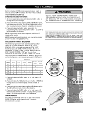
... will close the door, and the third button will light). 2. PROGRAMMING Your 315MHz Security✚® or dip switch remote control can be programmed to operate as follows: 1. To enter programming press the RADIO button on the radio receiver.) 5. You may set up this confirms that the remote control has been...
... will close the door, and the third button will light). 2. PROGRAMMING Your 315MHz Security✚® or dip switch remote control can be programmed to operate as follows: 1. To enter programming press the RADIO button on the radio receiver.) 5. You may set up this confirms that the remote control has been...
APT LOGIC 3 Manual
Page 20
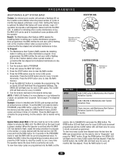
... are programmed into the MAS LED. Press the OPEN button; Press the MAS button to "Diagnostic" and press the "MAS" button. Logic 3.0 operators incorporate a self diagnostic feature built into the MAS, set the MAS, turn selector dial to PROGRAM, press MAS button, press the STOP button to...programmed, the MAS notifies the end user (with its current programmed value. The CLOSE LED will flash back the programmed settings. SELECTOR DIAL Operation will vary depending on wiring type 3-BUTTON STATION OPEN Maintenance Alert LED CLOSE STOP Press This OPEN CLOSE STOP To Get This Adds 5,000 ...
... are programmed into the MAS LED. Press the OPEN button; Press the MAS button to "Diagnostic" and press the "MAS" button. Logic 3.0 operators incorporate a self diagnostic feature built into the MAS, set the MAS, turn selector dial to PROGRAM, press MAS button, press the STOP button to...programmed, the MAS notifies the end user (with its current programmed value. The CLOSE LED will flash back the programmed settings. SELECTOR DIAL Operation will vary depending on wiring type 3-BUTTON STATION OPEN Maintenance Alert LED CLOSE STOP Press This OPEN CLOSE STOP To Get This Adds 5,000 ...
APT LOGIC 3 Manual
Page 21
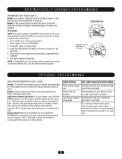
...devices will open the door beyond the mid stop height, then press the STOP button. 5. Turn the selector dial to complete programming. Operation will vary depending on logic board. 4. Example: To close the door. Benefit: The door opens to enable this new feature. To ...Program: 1. Once at least one of how to a midpoint between open position. To Program Manually (Method 1): SELECTOR DIAL 1. SELECTOR DIAL Operation will vary depending on the logic logic board. 4. Close the door. 2. Reversing devices are recommended for every 60 seconds programmed. Press the "...
...devices will open the door beyond the mid stop height, then press the STOP button. 5. Turn the selector dial to complete programming. Operation will vary depending on logic board. 4. Example: To close the door. Benefit: The door opens to enable this new feature. To ...Program: 1. Once at least one of how to a midpoint between open position. To Program Manually (Method 1): SELECTOR DIAL 1. SELECTOR DIAL Operation will vary depending on the logic logic board. 4. Close the door. 2. Reversing devices are recommended for every 60 seconds programmed. Press the "...
APT LOGIC 3 Manual
Page 22
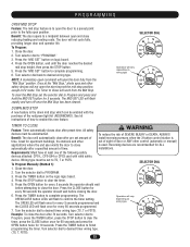
..., press the OPEN button and wait until TIMER LED flashes. 4. Benefit: The Auxiliary Reversal System reverses the operator upon hitting an obstruction, preventing excessive door and operator damage. By removing the centrifugal for 1/3 and 1/2 horsepower single phase motors, the leading cause of safety devices... activated by the Single Button Control (terminal 1) only. To deactivate the timer from the open position press the STOP button. SELECTOR DIAL Operation will flash once for 5 seconds until the door reaches the open or mid stop position. 5. The OPEN LED will flash once for...
..., press the OPEN button and wait until TIMER LED flashes. 4. Benefit: The Auxiliary Reversal System reverses the operator upon hitting an obstruction, preventing excessive door and operator damage. By removing the centrifugal for 1/3 and 1/2 horsepower single phase motors, the leading cause of safety devices... activated by the Single Button Control (terminal 1) only. To deactivate the timer from the open position press the STOP button. SELECTOR DIAL Operation will flash once for 5 seconds until the door reaches the open or mid stop position. 5. The OPEN LED will flash once for...
APT LOGIC 3 Manual
Page 23
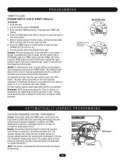
... rapidly. Turn dial to "PROGRAM." 3. Requirements: Must have the Red/Green warning light kit RDGRNCARD and must have at right. SELECTOR DIAL Operation will vary depending on logic board. 4. In the event the application requires the MRT be activated if timer setting is less than 10 seconds.)... not be manually learned for further details. See Red/Green warning light instructions for a longer duration follow steps below. 1. Benefit: If the operator does not meet its open or close limit within the set time it takes to open or close limit is activated Less than 10 seconds...
... rapidly. Turn dial to "PROGRAM." 3. Requirements: Must have the Red/Green warning light kit RDGRNCARD and must have at right. SELECTOR DIAL Operation will vary depending on logic board. 4. In the event the application requires the MRT be activated if timer setting is less than 10 seconds.)... not be manually learned for further details. See Red/Green warning light instructions for a longer duration follow steps below. 1. Benefit: If the operator does not meet its open or close limit within the set time it takes to open or close limit is activated Less than 10 seconds...


