Hardware Maintenance Manual - Notebook
Page 3
... 25 Screen blank mode 25 Putting your computer to sleep 25 Shutting down the computer 26 Lenovo G400s/G405s/G400s Touch/G500s/ G505s/G500s Touch 27 Specifications 27 Status indicators 30 Fn key combinations 32 FRU replacement notices 33 Screw notices 33 Removing and replacing an FRU 34 1010 Battery pack 35 1020 Dummy card 36...-side view 77 Bottom and Left-side view 78 Parts list 79 Overall 80 LCD FRUs 86 Keyboard 89 Miscellaneous parts 93 AC adapters 94 Screws 94 Power cords 95 Notices 99 Trademarks 100 iii
... 25 Screen blank mode 25 Putting your computer to sleep 25 Shutting down the computer 26 Lenovo G400s/G405s/G400s Touch/G500s/ G505s/G500s Touch 27 Specifications 27 Status indicators 30 Fn key combinations 32 FRU replacement notices 33 Screw notices 33 Removing and replacing an FRU 34 1010 Battery pack 35 1020 Dummy card 36...-side view 77 Bottom and Left-side view 78 Parts list 79 Overall 80 LCD FRUs 86 Keyboard 89 Miscellaneous parts 93 AC adapters 94 Screws 94 Power cords 95 Notices 99 Trademarks 100 iii
Hardware Maintenance Manual - Notebook
Page 9
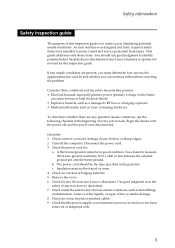
...not covered by this inspection guide is to the safety of any obvious non-Lenovo alterations. Check for damage (loose, broken, or sharp edges). 2. Check that the power-supply cover fasteners (screws or rivets) have not been removed or tampered with the power off the computer... Check for : a. As each machine was designed and built, required safety items were installed to measure third-wire ground continuity for any non-Lenovo alterations. 7. Disconnect the power cord. 3. Check for 0.1 ohm or less between the external ground pin and the frame ground. Consider these ...
...not covered by this inspection guide is to the safety of any obvious non-Lenovo alterations. Check for damage (loose, broken, or sharp edges). 2. Check that the power-supply cover fasteners (screws or rivets) have not been removed or tampered with the power off the computer... Check for : a. As each machine was designed and built, required safety items were installed to measure third-wire ground continuity for any non-Lenovo alterations. 7. Disconnect the power cord. 3. Check for 0.1 ohm or less between the external ground pin and the frame ground. Consider these ...
Hardware Maintenance Manual - Notebook
Page 23
... not be overwritten. • Replace an FRU only with a hardware defect, such as copying, saving, or formatting. If you replace FRUs, use new nylon-coated screws. • Be extremely careful during such write operations as cosmic radiation, electrostatic discharge, or software errors. Drives in the computer that have been altered.
... not be overwritten. • Replace an FRU only with a hardware defect, such as copying, saving, or formatting. If you replace FRUs, use new nylon-coated screws. • Be extremely careful during such write operations as cosmic radiation, electrostatic discharge, or software errors. Drives in the computer that have been altered.

Hardware Maintenance Manual - Notebook
Page 37
Lenovo G400s/G405s/G400s Touch/G500s/G505s/G500s Touch FRU replacement notices This section presents notices related to plastic Turn an additional 180° after the screw head touches the surface of the logic card: more than 180° (Cross-section) • Torque driver If you removed. If you have a torque screwdriver , refer to ...
Lenovo G400s/G405s/G400s Touch/G500s/G505s/G500s Touch FRU replacement notices This section presents notices related to plastic Turn an additional 180° after the screw head touches the surface of the logic card: more than 180° (Cross-section) • Torque driver If you removed. If you have a torque screwdriver , refer to ...
Hardware Maintenance Manual - Notebook
Page 38
...in which they are listed at the top of the interconnecting cables. DANGER Before removing any of the page. Any of the Lenovo G500s, unless otherwise stated. 34 Verify this section are loose inside the computer. Metallic parts or metal flakes can be removed before the...and certified. When turning a screw to replace an FRU, turn on the computer until you have to be damaged by the arrow in the procedures. Before touching it in the direction as shown in the figure. 7. Lenovo G400s/G405s/G400s Touch/G500s/G505s/G500s Touch Hardware Maintenance Manual Removing and ...
...in which they are listed at the top of the interconnecting cables. DANGER Before removing any of the page. Any of the Lenovo G500s, unless otherwise stated. 34 Verify this section are loose inside the computer. Metallic parts or metal flakes can be removed before the...and certified. When turning a screw to replace an FRU, turn on the computer until you have to be damaged by the arrow in the procedures. Before touching it in the direction as shown in the figure. 7. Lenovo G400s/G405s/G400s Touch/G500s/G505s/G500s Touch Hardware Maintenance Manual Removing and ...

Hardware Maintenance Manual - Notebook
Page 41
Removal steps of HDD/Memory/Mini PCI Express Card slot compartment cover Loosen the screws a that secure the compartment cover. Lenovo G400s/G405s/G400s Touch/G500s/G505s/G500s Touch 1030 Hard disk drive(HDD)/Memory/Mini PCI Express Card slot compartment cover For access, remove this FRU: • "1010 Battery pack" on page 35 ...
Removal steps of HDD/Memory/Mini PCI Express Card slot compartment cover Loosen the screws a that secure the compartment cover. Lenovo G400s/G405s/G400s Touch/G500s/G505s/G500s Touch 1030 Hard disk drive(HDD)/Memory/Mini PCI Express Card slot compartment cover For access, remove this FRU: • "1010 Battery pack" on page 35 ...
Hardware Maintenance Manual - Notebook
Page 42
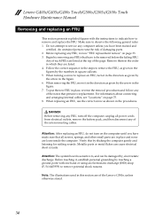
Lenovo G400s/G405s/G400s Touch/G500s/G505s/G500s Touch Hardware Maintenance Manual 1040 Hard disk drive For access, remove these FRUs in suspend mode. Improper handling can cause damages and permanent loss of hard disk drive Remove the frame fixing screws a . Removal steps of data. • Before...Attention: • Do not drop the hard disk drive or apply any physical shock to physical shock. a a a a Step a Screw (quantity) M2 × 5 mm, flat-head, nylok-coated (4) (G500s) M2 × 5 mm, flat-head, nylok-coated (4) (G400s) Color Black Black Torque 2.0 ~ 2.5 kgfcm 1.89 ~ 1.89...
Lenovo G400s/G405s/G400s Touch/G500s/G505s/G500s Touch Hardware Maintenance Manual 1040 Hard disk drive For access, remove these FRUs in suspend mode. Improper handling can cause damages and permanent loss of hard disk drive Remove the frame fixing screws a . Removal steps of data. • Before...Attention: • Do not drop the hard disk drive or apply any physical shock to physical shock. a a a a Step a Screw (quantity) M2 × 5 mm, flat-head, nylok-coated (4) (G500s) M2 × 5 mm, flat-head, nylok-coated (4) (G400s) Color Black Black Torque 2.0 ~ 2.5 kgfcm 1.89 ~ 1.89...

Hardware Maintenance Manual - Notebook
Page 44
Removal steps of hard disk drive (continued) Remove four screws d and detach the metal frame from the hard disk drive e. Lenovo G400s/G405s/G400s Touch/G500s/G505s/G500s Touch Hardware Maintenance Manual Figure 4. d d e d d Step d Screw (quantity) Color Torque M3 × 3 mm, flat-head, nylok-coated(4) White 2.88 ~ 2.95 kgfcm When installing: Make sure that the HDD connector is attached firmly. 40
Removal steps of hard disk drive (continued) Remove four screws d and detach the metal frame from the hard disk drive e. Lenovo G400s/G405s/G400s Touch/G500s/G505s/G500s Touch Hardware Maintenance Manual Figure 4. d d e d d Step d Screw (quantity) Color Torque M3 × 3 mm, flat-head, nylok-coated(4) White 2.88 ~ 2.95 kgfcm When installing: Make sure that the HDD connector is attached firmly. 40

Hardware Maintenance Manual - Notebook
Page 45
Lenovo G400s/G405s/G400s Touch/G500s/G505s/G500s Touch 1050 Optical drive For access, remove these FRUs in the direction shown by arrow c. 1 Step a Screw (quantity) Color M2.5 × 3 mm, flat-head, nylok-coated Black (1) (G500s) M 2 × 9 mm, flat-head, nylok-coated (1) Black (G400s) Torque 1.5 ~ 2.0 kgfcm 41 Pull the optical drive out in the direction shown by arrow...
Lenovo G400s/G405s/G400s Touch/G500s/G505s/G500s Touch 1050 Optical drive For access, remove these FRUs in the direction shown by arrow c. 1 Step a Screw (quantity) Color M2.5 × 3 mm, flat-head, nylok-coated Black (1) (G500s) M 2 × 9 mm, flat-head, nylok-coated (1) Black (G400s) Torque 1.5 ~ 2.0 kgfcm 41 Pull the optical drive out in the direction shown by arrow...

Hardware Maintenance Manual - Notebook
Page 48
... 1.89 ~ 1.96 kgfcm Remove the card in the direction shown by arrows. Lenovo G400s/G405s/G400s Touch/G500s/G505s/G500s Touch Hardware Maintenance Manual 1070 PCI Express Mini Card for wireless LAN/WAN Disconnect the two wireless LAN cables a, and then remove the screw b. 2 1 In step a, unplug the jacks by using the removal tool antenna RF...
... 1.89 ~ 1.96 kgfcm Remove the card in the direction shown by arrows. Lenovo G400s/G405s/G400s Touch/G500s/G505s/G500s Touch Hardware Maintenance Manual 1070 PCI Express Mini Card for wireless LAN/WAN Disconnect the two wireless LAN cables a, and then remove the screw b. 2 1 In step a, unplug the jacks by using the removal tool antenna RF...

Hardware Maintenance Manual - Notebook
Page 50
Lenovo G400s/G405s/G400s Touch/G500s/G505s/G500s Touch Hardware Maintenance Manual 1080 Fan assembly For access, remove these FRUs in the direction shown by arrow b . 1 1 b When installing: Make sure that the fan connector is attached firmly to the system board. Step a Screw (quantity) Color Torque M2 &#...215; 3.5 mm, flat-head, nylok-coated (2) Black 46 Removal steps of fan assembly Remove two screws a , unplug the fan connector in order: • "1010 Battery pack" on...
Lenovo G400s/G405s/G400s Touch/G500s/G505s/G500s Touch Hardware Maintenance Manual 1080 Fan assembly For access, remove these FRUs in the direction shown by arrow b . 1 1 b When installing: Make sure that the fan connector is attached firmly to the system board. Step a Screw (quantity) Color Torque M2 &#...215; 3.5 mm, flat-head, nylok-coated (2) Black 46 Removal steps of fan assembly Remove two screws a , unplug the fan connector in order: • "1010 Battery pack" on...
Hardware Maintenance Manual - Notebook
Page 51
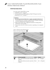
Lenovo G400s/G405s/G400s Touch/G500s/G505s/G500s Touch 1090 Keyboard For access, remove these FRUs in order: • "1010 Battery pack" on page 35 • "1030 Hard disk drive(HDD)/Memory/Mini PCI Express Card slot compartment cover" on page 37 • "1080 Fan assembly" on page 46 Figure 9. Removal steps of keyboard G500s: Remove screws a . 1 1 1 Step a Screw (quantity) M2 × 5 mm, flat-head, nylok-coated (3) (G500s) M2 × 9 mm, flat-head, nylok-coated (3) (G400s) Color Black Black Torque 1.5 ~ 2.0 kgfcm 1.89 ~ 1.98 kgfcm 47
Lenovo G400s/G405s/G400s Touch/G500s/G505s/G500s Touch 1090 Keyboard For access, remove these FRUs in order: • "1010 Battery pack" on page 35 • "1030 Hard disk drive(HDD)/Memory/Mini PCI Express Card slot compartment cover" on page 37 • "1080 Fan assembly" on page 46 Figure 9. Removal steps of keyboard G500s: Remove screws a . 1 1 1 Step a Screw (quantity) M2 × 5 mm, flat-head, nylok-coated (3) (G500s) M2 × 9 mm, flat-head, nylok-coated (3) (G400s) Color Black Black Torque 1.5 ~ 2.0 kgfcm 1.89 ~ 1.98 kgfcm 47

Hardware Maintenance Manual - Notebook
Page 53
Lenovo G400s/G405s/G400s Touch/G500s/G505s/G500s Touch Figure 9. Removal steps of keyboard (continued) d e f G400s: Remove the screws a. 1 1 Step a Screw (quantity) M2 × 9 mm, flat-head, nylok-coated (2) (G400s) Color Black Torque 1.89 ~ 1.98 kgfcm 49
Lenovo G400s/G405s/G400s Touch/G500s/G505s/G500s Touch Figure 9. Removal steps of keyboard (continued) d e f G400s: Remove the screws a. 1 1 Step a Screw (quantity) M2 × 9 mm, flat-head, nylok-coated (2) (G400s) Color Black Torque 1.89 ~ 1.98 kgfcm 49

Hardware Maintenance Manual - Notebook
Page 56
Lenovo G400s/G405s/G400s Touch/G500s/G505s/G500s Touch Hardware Maintenance Manual 1100 Keyboard bezel For access, remove these FRUs in order: • "1010 Battery pack" on page 35 • "1030 Hard disk drive(... PCI Express Mini Card for wireless LAN/WAN" on page 44 • "1080 Fan assembly" on page 46 • "1090 Keyboard" on the bottom. 1 1 1 2 1 2 1 1 1 1 Step a a Screw (quantity) Color M2.5 × 6 mm, flat-head, nylok-coated (8) Black M2.5 × 3 mm, flat-head, nylok-coated (2) Black Torque 2.38 ~ 2.48 kgfcm 1.0 ~ 1.5 kgfcm 52 Removal...
Lenovo G400s/G405s/G400s Touch/G500s/G505s/G500s Touch Hardware Maintenance Manual 1100 Keyboard bezel For access, remove these FRUs in order: • "1010 Battery pack" on page 35 • "1030 Hard disk drive(... PCI Express Mini Card for wireless LAN/WAN" on page 44 • "1080 Fan assembly" on page 46 • "1090 Keyboard" on the bottom. 1 1 1 2 1 2 1 1 1 1 Step a a Screw (quantity) Color M2.5 × 6 mm, flat-head, nylok-coated (8) Black M2.5 × 3 mm, flat-head, nylok-coated (2) Black Torque 2.38 ~ 2.48 kgfcm 1.0 ~ 1.5 kgfcm 52 Removal...
Hardware Maintenance Manual - Notebook
Page 57
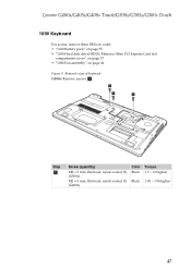
c When installing: Make sure that the power board connector and touch pad cable are attached firmly. 53 Removal steps of keyboard (continued) G400s: Remove six screws a and three screws b on the bottom. 1 1 1 2 2 2 1 1 1 Step a a Screw (quantity) Color M2.5 × 6 mm, flat-head, nylok-coated (6) Black M2 × 3 mm, flat-head, nylok-coated (3) Black Torque 2.38 ~ 2.5 kgfcm 1.0 ~ 1.5 kgfcm G500s: Detach the power board connector, and touch pad cable in the direction shown by arrow c . Lenovo G400s/G405s/G400s Touch/G500s/G505s/G500s Touch Figure 10.
c When installing: Make sure that the power board connector and touch pad cable are attached firmly. 53 Removal steps of keyboard (continued) G400s: Remove six screws a and three screws b on the bottom. 1 1 1 2 2 2 1 1 1 Step a a Screw (quantity) Color M2.5 × 6 mm, flat-head, nylok-coated (6) Black M2 × 3 mm, flat-head, nylok-coated (3) Black Torque 2.38 ~ 2.5 kgfcm 1.0 ~ 1.5 kgfcm G500s: Detach the power board connector, and touch pad cable in the direction shown by arrow c . Lenovo G400s/G405s/G400s Touch/G500s/G505s/G500s Touch Figure 10.

Hardware Maintenance Manual - Notebook
Page 60
f a a a a d e c b Step Screw (quantity) a M2.5 × 3 mm, flat-head, nylok-coated (4) Color Torque Black 1.5 ~ 2.0 kgfcm 56 Removal steps of system board G500s: Loosen the screws a . Detach the LCD connector b , optical disk drive board connector, IO board and LED board connector in the direction shown by arrows c d , unplug the speakers and DC-IN cable connector in the direction shown by arrows e f . Lenovo G400s/G405s/G400s Touch/G500s/G505s/G500s Touch Hardware Maintenance Manual Figure 11.
f a a a a d e c b Step Screw (quantity) a M2.5 × 3 mm, flat-head, nylok-coated (4) Color Torque Black 1.5 ~ 2.0 kgfcm 56 Removal steps of system board G500s: Loosen the screws a . Detach the LCD connector b , optical disk drive board connector, IO board and LED board connector in the direction shown by arrows c d , unplug the speakers and DC-IN cable connector in the direction shown by arrows e f . Lenovo G400s/G405s/G400s Touch/G500s/G505s/G500s Touch Hardware Maintenance Manual Figure 11.

Hardware Maintenance Manual - Notebook
Page 61
Detach LCD connector in the direction shown by arrow b , USB board connector in the direction shown by arrow c . Step Screw (quantity) a M2.5 × 3 mm, flat-head, nylok-coated (2) Color Torque Black 2.38 ~2.48 kgfcm 57 Removal steps of system board G400s: Loosen two screws a . Unplug the DC-IN cable and speakers connectors in the direction shown by arrows d e. d a a e c b When installing: Make sure that all the connectors are attached firmly. Lenovo G400s/G405s/G400s Touch/G500s/G505s/G500s Touch Figure 11.
Detach LCD connector in the direction shown by arrow b , USB board connector in the direction shown by arrow c . Step Screw (quantity) a M2.5 × 3 mm, flat-head, nylok-coated (2) Color Torque Black 2.38 ~2.48 kgfcm 57 Removal steps of system board G400s: Loosen two screws a . Unplug the DC-IN cable and speakers connectors in the direction shown by arrows d e. d a a e c b When installing: Make sure that all the connectors are attached firmly. Lenovo G400s/G405s/G400s Touch/G500s/G505s/G500s Touch Figure 11.
Hardware Maintenance Manual - Notebook
Page 63
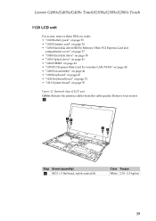
Remove four screws a. aa aa Step Screw (quantity) a M2.5 × 5 flat-head, nylok-coated (4) Color Torque White 2.38 ~2.5 kgfcm 59 Removal steps of LCD unit G500s: Release the antenna cables from the cable guides. Lenovo G400s/G405s/G400s Touch/G500s/G505s/G500s Touch 1120 LCD unit For access, remove these FRUs in order: • "1010 Battery pack" on page...
Remove four screws a. aa aa Step Screw (quantity) a M2.5 × 5 flat-head, nylok-coated (4) Color Torque White 2.38 ~2.5 kgfcm 59 Removal steps of LCD unit G500s: Release the antenna cables from the cable guides. Lenovo G400s/G405s/G400s Touch/G500s/G505s/G500s Touch 1120 LCD unit For access, remove these FRUs in order: • "1010 Battery pack" on page...

Hardware Maintenance Manual - Notebook
Page 64
... the antenna cables from the cable guides. Remove four screws a. aa aa Step a Screw (quantity) M2.5 × 4 mm, flat-head, nylok-coated (4) Color Black Torque 2.38 ~ 2.5 kgfcm When installing: • Route the antenna cables along the cable guides. 60 Lenovo G400s/G405s/G400s Touch/G500s/G505s/G500s Touch Hardware Maintenance Manual Figure 12. As you attach the...
... the antenna cables from the cable guides. Remove four screws a. aa aa Step a Screw (quantity) M2.5 × 4 mm, flat-head, nylok-coated (4) Color Black Torque 2.38 ~ 2.5 kgfcm When installing: • Route the antenna cables along the cable guides. 60 Lenovo G400s/G405s/G400s Touch/G500s/G505s/G500s Touch Hardware Maintenance Manual Figure 12. As you attach the...

Hardware Maintenance Manual - Notebook
Page 67
a a b a b Step a Screw (quantity) Color M2.0 × 3.2 mm, flat-head, nylok-coated (3) Black M2.0 × 3.5 mm, flat-head, nylok-coated (2) Black Torque 1.0 ~ 1.5 kgfcm 1.0 ~ 1.5 kgfcm 63 Removal steps of heat sink assembly Loosen three screws a and two screws b to lift the heat sink assembly. Lenovo G400s/G405s/G400s Touch/G500s/G505s/G500s Touch Figure 13.
a a b a b Step a Screw (quantity) Color M2.0 × 3.2 mm, flat-head, nylok-coated (3) Black M2.0 × 3.5 mm, flat-head, nylok-coated (2) Black Torque 1.0 ~ 1.5 kgfcm 1.0 ~ 1.5 kgfcm 63 Removal steps of heat sink assembly Loosen three screws a and two screws b to lift the heat sink assembly. Lenovo G400s/G405s/G400s Touch/G500s/G505s/G500s Touch Figure 13.

