
Owner's Manual
Page 3
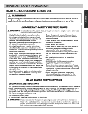
... adapter or extension cord. • Do not remove ground prong. • If you are in accordance with controls. • Do not repair or replace any part of life. For your washer. This will be exposed to play on all instructions before using the washing machine, turn on or in this time...
... adapter or extension cord. • Do not remove ground prong. • If you are in accordance with controls. • Do not repair or replace any part of life. For your washer. This will be exposed to play on all instructions before using the washing machine, turn on or in this time...
Owner's Manual
Page 18
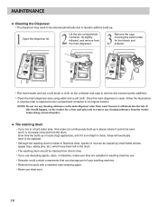
...; If you use descaling agents, dyes, or bleaches, make sure they are suitable for washing machine use. • Descaler could contain components that can damage part of rust can continuously build up in places where it cannot be seen and it is not easily removed from the main dispenser. 3 Remove the...
...; If you use descaling agents, dyes, or bleaches, make sure they are suitable for washing machine use. • Descaler could contain components that can damage part of rust can continuously build up in places where it cannot be seen and it is not easily removed from the main dispenser. 3 Remove the...
Service Manual
Page 3
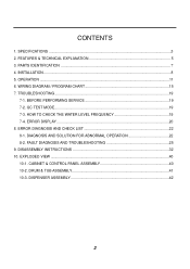
...-3. CONTENTS 1. OPERATION ...11 6. ERROR DIAGNOSIS AND CHECK LIST 22 8-1. FEATURES & TECHNICAL EXPLANATION 5 3. BEFORE PERFORMING SERVICE 19 7-2. QC TEST MODE...19 7-3. FAULT DIAGNOSIS AND TROUBLESHOOTING 25 9. PARTS IDENTIFICATION ...7 4. SPECIFICATIONS ...3 2. WIRING DIAGRAM / PROGRAM CHART 15 7. TROUBLESHOOTING...19 7-1. ERROR DISPLAY ...20 8. CABINET & CONTROL PANEL ASSEMBLY 40 10-2. DISPENSER ASSEMBLY 42 2
...-3. CONTENTS 1. OPERATION ...11 6. ERROR DIAGNOSIS AND CHECK LIST 22 8-1. FEATURES & TECHNICAL EXPLANATION 5 3. BEFORE PERFORMING SERVICE 19 7-2. QC TEST MODE...19 7-3. FAULT DIAGNOSIS AND TROUBLESHOOTING 25 9. PARTS IDENTIFICATION ...7 4. SPECIFICATIONS ...3 2. WIRING DIAGRAM / PROGRAM CHART 15 7. TROUBLESHOOTING...19 7-1. ERROR DISPLAY ...20 8. CABINET & CONTROL PANEL ASSEMBLY 40 10-2. DISPENSER ASSEMBLY 42 2

Service Manual
Page 8
3. PARTS IDENTIFICATION • If the supply cord is damaged, it must be replaced by the manufacturer or its authorized service technician in order to avoid a hazard. (PLC Modem) ACCESSORIES 7
3. PARTS IDENTIFICATION • If the supply cord is damaged, it must be replaced by the manufacturer or its authorized service technician in order to avoid a hazard. (PLC Modem) ACCESSORIES 7
Service Manual
Page 20
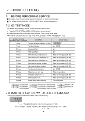
...and the controls must be in . 7-2. The digits indicate the water level frequency ( x.1 kHz ). Number of electric shock when disconnecting parts for 3 sec. 11 times Circulation pump turns on. 12 times Drain pump turns on for while troubleshooting. WM2411HW WM2432HW WD-12210(5)BD WM2011HS... / WM2011HW WM2032HS / WM2032HW WM0532HW / WD-10210BD WM1811CW WM1832CW 7-3. Display Status rpm (40~50) rpm rpm Water level frequency (25~65) Water level ...
...and the controls must be in . 7-2. The digits indicate the water level frequency ( x.1 kHz ). Number of electric shock when disconnecting parts for 3 sec. 11 times Circulation pump turns on. 12 times Drain pump turns on for while troubleshooting. WM2411HW WM2432HW WD-12210(5)BD WM2011HS... / WM2011HW WM2032HS / WM2032HW WM0532HW / WD-10210BD WM1811CW WM1832CW 7-3. Display Status rpm (40~50) rpm rpm Water level frequency (25~65) Water level ...
Service Manual
Page 26
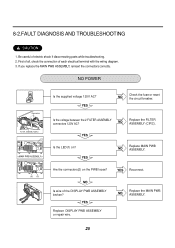
... AC? NO Replace the MAIN PWB ASSEMBLY. 25 NO Replace the FILTER ASSEMBLY (CIRC). First of all, check the connection of electric shock if disconnecting parts while troubleshooting. 2. NO Is wire of the DISPLAY PWB ASSEMBLY broken?
... AC? NO Replace the MAIN PWB ASSEMBLY. 25 NO Replace the FILTER ASSEMBLY (CIRC). First of all, check the connection of electric shock if disconnecting parts while troubleshooting. 2. NO Is wire of the DISPLAY PWB ASSEMBLY broken?

Service Manual
Page 34
Release the 5 hoses. 3. Unplug the 2 connectors. 33 Unscrew the screw from the valves. ¡ Wire color : ¥L WH-BK ¥M OR-BK ¥N WH-BK ¥O GY-BK ¥P BL-BK 1. Disassemble the 5 connectors from the top plate. 2. Unscrew the nut at the lower part of the dispenser. 4. Unscrew the 4 screws on the holder. 5. 1. Disassemble the 5 hose clamps. 2.
Release the 5 hoses. 3. Unplug the 2 connectors. 33 Unscrew the screw from the valves. ¡ Wire color : ¥L WH-BK ¥M OR-BK ¥N WH-BK ¥O GY-BK ¥P BL-BK 1. Disassemble the 5 connectors from the top plate. 2. Unscrew the nut at the lower part of the dispenser. 4. Unscrew the 4 screws on the holder. 5. 1. Disassemble the 5 hose clamps. 2.


