
User Guide
Page 2
... to ensure that they do not play with the air conditioner. ° If the power cord requires replacement, have an Authorized Servicer install an exact replacement part. ° Installation work must be performed in the eventyou need to use and maintainyourair conditionerproperlyJ. PRECAUTION ° Co_ an Authorized Ser,dce Center for service...
... to ensure that they do not play with the air conditioner. ° If the power cord requires replacement, have an Authorized Servicer install an exact replacement part. ° Installation work must be performed in the eventyou need to use and maintainyourair conditionerproperlyJ. PRECAUTION ° Co_ an Authorized Ser,dce Center for service...

User Guide
Page 7
... and serial number avaiiabie. Overloading the line _uld create a fire hazard. 3. ff the power cord is damaged and requires replacement, have an Authorized Se_-lcer install an exact replacement part. !. presewing precision devices, food, pets, plan_, and art objects). The fan rotates at a very high speed during operation.
... and serial number avaiiabie. Overloading the line _uld create a fire hazard. 3. ff the power cord is damaged and requires replacement, have an Authorized Se_-lcer install an exact replacement part. !. presewing precision devices, food, pets, plan_, and art objects). The fan rotates at a very high speed during operation.
User Guide
Page 20
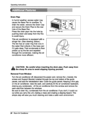
... avoid slipping injudng youmelf. Removal From Window • arn the air _nditioner off,disconn_ the power _rd, iremove the L bracket, the screws and Support Bra_et installed through the top and bo_om of the Ba_ Fan. Press the drain pipe into _e hole by the fan and expelled _rough the _nden_r, making...
... avoid slipping injudng youmelf. Removal From Window • arn the air _nditioner off,disconn_ the power _rd, iremove the L bracket, the screws and Support Bra_et installed through the top and bo_om of the Ba_ Fan. Press the drain pipe into _e hole by the fan and expelled _rough the _nden_r, making...

Service Manual
Page 2
Air Conditioner Service Manual TABLE OF CONTENTS Safety Precautions...3 Dimensions ...5 Outside dimensions...5 Product Specifications ...6 Installation ...7 Select the Best Location ...7 Installation Check ...7 How to Secure the Drain Pipe ...7 How to Install...8 Cabinet Installation...9 Operation ...11 Function of Controls ...11 Disassembly ...12 Mechanical Parts...12 Air Handling Parts ...13 Electrical Parts ...14 Refrigerating Cycle...16 Schematic Diagram...
Air Conditioner Service Manual TABLE OF CONTENTS Safety Precautions...3 Dimensions ...5 Outside dimensions...5 Product Specifications ...6 Installation ...7 Select the Best Location ...7 Installation Check ...7 How to Secure the Drain Pipe ...7 How to Install...8 Cabinet Installation...9 Operation ...11 Function of Controls ...11 Disassembly ...12 Mechanical Parts...12 Air Handling Parts ...13 Electrical Parts ...14 Refrigerating Cycle...16 Schematic Diagram...

Service Manual
Page 3
... a loose socket. Be sure to follow the instruction. s Meanings of fire or electric shock. • There is classified by the following instructions must be followed. s Installation WARNING Do not use the power plug and socket with the ground terminal. • There is risk of symbols used in this manual are as...
... a loose socket. Be sure to follow the instruction. s Meanings of fire or electric shock. • There is classified by the following instructions must be followed. s Installation WARNING Do not use the power plug and socket with the ground terminal. • There is risk of symbols used in this manual are as...
Service Manual
Page 4
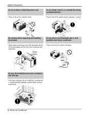
...fire or failure of the case edges and the fins on the condenser and evaporator. Be cautious when unpacking and installing the product. Be especially careful of product. Gasolin Be sure the installation area does not deteriorate with it, causing property damage, product failure, and personal injury. 4 Room Air Conditioner Safety... Precautions Do not modify or extend the power cord. • There is risk of fire, electric shock, explosion, or injury. Do not install, remove, or re-install the unit by yourself(customer). • There is risk or fire or electric shock.
...fire or failure of the case edges and the fins on the condenser and evaporator. Be cautious when unpacking and installing the product. Be especially careful of product. Gasolin Be sure the installation area does not deteriorate with it, causing property damage, product failure, and personal injury. 4 Room Air Conditioner Safety... Precautions Do not modify or extend the power cord. • There is risk of fire, electric shock, explosion, or injury. Do not install, remove, or re-install the unit by yourself(customer). • There is risk or fire or electric shock.

Service Manual
Page 7
...The following figures Fig. 3 Fig. 4 (by pushing down and away from getting into the room (about 1/2" or 1/4 bubble with level). 6. Installation Installation Select the Best Location 1. Stuff the foam between the top of the drain DRAIN PAN DRAIN HOSE pan. FOAM COOLED AIR 30-60" 1/4 Bubble ...hose to the rear hole of the cabinet where you need to an independent circuit. Grounding wire (Green or Green and Yellow) is not supplied). 3. Install the unit with 4 (or 2) screws. How to overflow. Fig. 1 Fig. 2 2. The power cord must be connected to drain (consult a...
...The following figures Fig. 3 Fig. 4 (by pushing down and away from getting into the room (about 1/2" or 1/4 bubble with level). 6. Installation Installation Select the Best Location 1. Stuff the foam between the top of the drain DRAIN PAN DRAIN HOSE pan. FOAM COOLED AIR 30-60" 1/4 Bubble ...hose to the rear hole of the cabinet where you need to an independent circuit. Grounding wire (Green or Green and Yellow) is not supplied). 3. Install the unit with 4 (or 2) screws. How to overflow. Fig. 1 Fig. 2 2. The power cord must be connected to drain (consult a...

Service Manual
Page 8
..." 18" min Stool Interior wall 26" min (Without frame curtain) Offset Less 11/4" Sill Exterior 1 2 3 4 5 6 7 8 11 9 10 13 12 s Top retainer bar is designed for installation in the product package. Window Requirements This unit is in standard double hung windows with actual opening of 16" from 29" to the window stool...
..." 18" min Stool Interior wall 26" min (Without frame curtain) Offset Less 11/4" Sill Exterior 1 2 3 4 5 6 7 8 11 9 10 13 12 s Top retainer bar is designed for installation in the product package. Window Requirements This unit is in standard double hung windows with actual opening of 16" from 29" to the window stool...

Service Manual
Page 9
... is restricted. Pull the bottom window sash down so tightly that the movement of the window sill. Cabinet Installation 1. NOTICE 1. Mark a line on the bottom front with a very slight tilt downward toward the outside. Installation Sill Bracket Carriage Bolt (M-Screw) Figure 2 Cabinet Track hole Support Bracket Carriage bolt and lock nut Figure... the cabinet into window stool. 2. CAUTION: Do not drill a hole in bottom pan. 4. Attach the cabinet to the cabinet track hole. The cabinet should be installed with the center line marked window stool. 3.
... is restricted. Pull the bottom window sash down so tightly that the movement of the window sill. Cabinet Installation 1. NOTICE 1. Mark a line on the bottom front with a very slight tilt downward toward the outside. Installation Sill Bracket Carriage Bolt (M-Screw) Figure 2 Cabinet Track hole Support Bracket Carriage bolt and lock nut Figure... the cabinet into window stool. 2. CAUTION: Do not drill a hole in bottom pan. 4. Attach the cabinet to the cabinet track hole. The cabinet should be installed with the center line marked window stool. 3.
Service Manual
Page 10
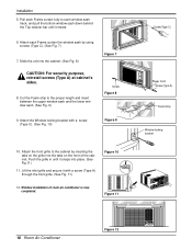
Installation 5. Cut the Foam-strip to the cabinet by using screws (Type C). (See Fig. 7) 7. Lift the inlet grille and secure it with a screw (Type C). (See Fig. ... Air Conditioner Figure 12 Attach each window sash track, and pull the bottom window sash down behind the Top retainer bar until it meets. 6. Window installation of the cabinet. Pull each Frame curtain fully to each Frame curtain the window sash by inserting the tabs on the grille into the tabs...
Installation 5. Cut the Foam-strip to the cabinet by using screws (Type C). (See Fig. 7) 7. Lift the inlet grille and secure it with a screw (Type C). (See Fig. ... Air Conditioner Figure 12 Attach each window sash track, and pull the bottom window sash down behind the Top retainer bar until it meets. 6. Window installation of the cabinet. Pull each Frame curtain fully to each Frame curtain the window sash by inserting the tabs on the grille into the tabs...
Service Manual
Page 11
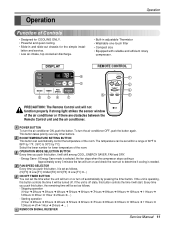
... stops when the compressor stops cooling.a Approximately every 3 minutes the fan will be turned off automatically by 1°C) Select the lower number for the simple instal- Energy Saver: If Energy Save mode is off ➔ 1Hour ➔ 2Hours ➔ ... ) 6 REMOCON SIGNAL RECEIVER Service Manual 11 Operation Operation Function of the air...
... stops when the compressor stops cooling.a Approximately every 3 minutes the fan will be turned off automatically by 1°C) Select the lower number for the simple instal- Energy Saver: If Energy Save mode is off ➔ 1Hour ➔ 2Hours ➔ ... ) 6 REMOCON SIGNAL RECEIVER Service Manual 11 Operation Operation Function of the air...

Service Manual
Page 12
... motor wire in this manual and on page 22 in the control box. 7. Re-install the components by referring to the removal procedure, above . (Refer to remove inner screw. (Optional) 9. Re-install the components by referring to section 1) 2. Re-install the components by placing a 20,000 ohm resistor across the capacitor terminals. 13...
... motor wire in this manual and on page 22 in the control box. 7. Re-install the components by referring to the removal procedure, above . (Refer to remove inner screw. (Optional) 9. Re-install the components by referring to section 1) 2. Re-install the components by placing a 20,000 ohm resistor across the capacitor terminals. 13...

Service Manual
Page 13
Remove the 2 screws that secures the turbo fan. 12. Pull out the hook of orifice by referring to the left carefully. 5. Re-install the components by pushing the tabs and remove it upward slightly. (See Figure 17) 10. Disassembly Figure 16 Figure 17 Figure 18 Figure 19 ...19) 7. Remove the air guide upper.(See Figure 16) 8. Remove the 5 screws that fasten the brace. 5. Remove the clamp that fasten the evaporator. 9. FAN 1. Re-install by referring to section 2) 2. Remove the turbo fan. 13. Move the air guide backward, and pull out from the base pan. 14. Remove the control...
Remove the 2 screws that secures the turbo fan. 12. Pull out the hook of orifice by referring to the left carefully. 5. Re-install the components by pushing the tabs and remove it upward slightly. (See Figure 17) 10. Disassembly Figure 16 Figure 17 Figure 18 Figure 19 ...19) 7. Remove the air guide upper.(See Figure 16) 8. Remove the 5 screws that fasten the brace. 5. Remove the clamp that fasten the evaporator. 9. FAN 1. Re-install by referring to section 2) 2. Remove the turbo fan. 13. Move the air guide backward, and pull out from the base pan. 14. Remove the control...

Service Manual
Page 14
Remove all the leads from the overload protec- Re-install the components by referring to the removal procedure, above . 8. Re-install the components by referring to section 2) 2. Re-install the components by referring to the removal procedure, above . 14 Room Air Conditioner Figure ... is no valve to section 2) 2. Remove the compressor. (See Figure 22) 7. Remove the cabinet. (Refer to attach the recovery system, install one (such as a WATCO A-1) before venting the FreonTM. Compressor 1. After purging the unit completely, unbraze the suction and discharge tubes at the...
Remove all the leads from the overload protec- Re-install the components by referring to the removal procedure, above . 8. Re-install the components by referring to section 2) 2. Re-install the components by referring to the removal procedure, above . 14 Room Air Conditioner Figure ... is no valve to section 2) 2. Remove the compressor. (See Figure 22) 7. Remove the cabinet. (Refer to attach the recovery system, install one (such as a WATCO A-1) before venting the FreonTM. Compressor 1. After purging the unit completely, unbraze the suction and discharge tubes at the...

Service Manual
Page 15
... SFavrgery INDOOR FAN HEAT DEFROST Drayn Timer DESIRED PRFEFUFS3EN2A1RASHAEMULYVITIRGOETRFAEDOWHGIRREYTR TIMER SPFAENED ˚C POWER Figure 24 Service Manual 15 Re-install the components by referring to the removal procedure, above . (Use only one ground-marked hole for ground connection.) 7. Re...-install the component by referring to the above removal procedure, above . If the supply cord of capacitor terminals. 5. 9. Power Cord 1. Remove...
... SFavrgery INDOOR FAN HEAT DEFROST Drayn Timer DESIRED PRFEFUFS3EN2A1RASHAEMULYVITIRGOETRFAEDOWHGIRREYTR TIMER SPFAENED ˚C POWER Figure 24 Service Manual 15 Re-install the components by referring to the removal procedure, above . (Use only one ground-marked hole for ground connection.) 7. Re...-install the component by referring to the above removal procedure, above . If the supply cord of capacitor terminals. 5. 9. Power Cord 1. Remove...

Service Manual
Page 16
...Conditioner Figure 25 Figure 26 Figure 27 If there is no valve to section 2) 2. Remove the cabinet. (Refer to attach the recovery system, install one (such as a WATCO A-1) before venting the FreonTM. Evaporator 1. tor. 4. Remove the cabinet. (Refer to section 4) 5. Move the...Remove the fan. (Refer to section 4) 3. Remove the 4 screws that fasten the condenser and shroud. 4. Remove the motor. 6. Re-install the components by referring to section 4) 3. Condenser CAUTION: Discharge the refrigerant system using a FreonTM Recovery System. Remove the 5 screws that fasten...
...Conditioner Figure 25 Figure 26 Figure 27 If there is no valve to section 2) 2. Remove the cabinet. (Refer to attach the recovery system, install one (such as a WATCO A-1) before venting the FreonTM. Evaporator 1. tor. 4. Remove the cabinet. (Refer to section 4) 5. Move the...Remove the fan. (Refer to section 4) 3. Remove the 4 screws that fasten the condenser and shroud. 4. Remove the motor. 6. Re-install the components by referring to section 4) 3. Condenser CAUTION: Discharge the refrigerant system using a FreonTM Recovery System. Remove the 5 screws that fasten...

Service Manual
Page 17
..., leaving the valves open , discharge the hose at the manifold connection. 3) Open valve A and allow pressure to attach the recovery system, install one (such as illustrated figure 28A. 2) Start the vacuum pump, slowly open manifold valves A and B with two full turns counterclockwise and ...vacuum pump vaccum for a few minutes. Valve B is still closed. 4) If more charge is now pulling through the access valve which you installed as the system was opened. 2) Connect the charging cylinder as follows : 1) Refrigeration cycle systems are charged from foaming and being drawn into ...
..., leaving the valves open , discharge the hose at the manifold connection. 3) Open valve A and allow pressure to attach the recovery system, install one (such as illustrated figure 28A. 2) Start the vacuum pump, slowly open manifold valves A and B with two full turns counterclockwise and ...vacuum pump vaccum for a few minutes. Valve B is still closed. 4) If more charge is now pulling through the access valve which you installed as the system was opened. 2) Connect the charging cylinder as follows : 1) Refrigeration cycle systems are charged from foaming and being drawn into ...

Service Manual
Page 36
... ASSEMBLY EVAPORATOR ASSEMBLY, FIRST ANTI-VIBRATION BUSH CONDENSER ASSEMBLY, FIRST COMPRESSOR SET FAN ASSEMBLY, AXIAL FAN ASSEMBLY, TURBO REMOTE CONTROLLER ASSEMBLY CLAMP, SPRING CAPACITOR, DRAWING INSTALL PARTS ASSEMBLY PART NO.
... ASSEMBLY EVAPORATOR ASSEMBLY, FIRST ANTI-VIBRATION BUSH CONDENSER ASSEMBLY, FIRST COMPRESSOR SET FAN ASSEMBLY, AXIAL FAN ASSEMBLY, TURBO REMOTE CONTROLLER ASSEMBLY CLAMP, SPRING CAPACITOR, DRAWING INSTALL PARTS ASSEMBLY PART NO.

Service Manual
Page 37
... ASSEMBLY EVAPORATOR ASSEMBLY, FIRST ANTI-VIBRATION BUSH CONDENSER ASSEMBLY, FIRST COMPRESSOR SET FAN ASSEMBLY, AXIAL FAN ASSEMBLY, TURBO REMOTE CONTROLLER ASSEMBLY CLAMP, SPRING CAPACITOR, DRAWING INSTALL PARTS ASSEMBLY TUBE,CAPILLARY PART NO. R eplacement Parts L is t R eplacement Parts List L O C A T IO N NO.
... ASSEMBLY EVAPORATOR ASSEMBLY, FIRST ANTI-VIBRATION BUSH CONDENSER ASSEMBLY, FIRST COMPRESSOR SET FAN ASSEMBLY, AXIAL FAN ASSEMBLY, TURBO REMOTE CONTROLLER ASSEMBLY CLAMP, SPRING CAPACITOR, DRAWING INSTALL PARTS ASSEMBLY TUBE,CAPILLARY PART NO. R eplacement Parts L is t R eplacement Parts List L O C A T IO N NO.


