Owner's Manual
Page 3
... Tubes Assembly Method 16 8. Working Principles...45 2. PARTS IDENTIFICATION ...5 3. Fan Shroud Grille...14 5. Ice maker Assembly...14 6. Disassemble of Tray Drip 18 10. Explanation for PCB circuit 30 7. Ice maker Troubleshooting 49 4. CIRCUIT DIAGRAM...51 9. HOW TO DISASSEMBLY AND ASSEMBLY 11 1. Disassemble of fan...Icemaker Circuit...50 8. Dispenser...19 5. EXPLODED VIEW ...132 - 2 - Refrigerator Shelves...8 4. Handle Removal...12 3. SPECIFICATIONS ...4 2. How to ice maker 9 4. DISASSEMBLY ...6 1. CONTENTS SAFETY PRECAUTIONS ...3 1. Freezer Shelf...8 5.
... Tubes Assembly Method 16 8. Working Principles...45 2. PARTS IDENTIFICATION ...5 3. Fan Shroud Grille...14 5. Ice maker Assembly...14 6. Disassemble of Tray Drip 18 10. Explanation for PCB circuit 30 7. Ice maker Troubleshooting 49 4. CIRCUIT DIAGRAM...51 9. HOW TO DISASSEMBLY AND ASSEMBLY 11 1. Disassemble of fan...Icemaker Circuit...50 8. Dispenser...19 5. EXPLODED VIEW ...132 - 2 - Refrigerator Shelves...8 4. Handle Removal...12 3. SPECIFICATIONS ...4 2. How to ice maker 9 4. DISASSEMBLY ...6 1. CONTENTS SAFETY PRECAUTIONS ...3 1. Freezer Shelf...8 5.
Owner's Manual
Page 5
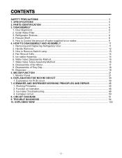
SPECIFICATIONS GENERAL FEATURES MODELS LSC27914SB /01 LSC27914SW /01 LSC27914TT /01 LSC27914ST /01 FREEZER REFRIGERATOR SPECIFICATIONS Color Dimensions Net Weight Capacity Refrigerant Climate class Rated Rating Cooling System Temperature Control Defrosting ... Oil Drier Capillary Tube First Defrost Defrost Cycle Desfrosting Device Anti-freezing Heater Case Material Door Material Handle Type Display Graphic Basket Lamp Shelf Tray meat Egg Bank Ice Maker Basket Lamp Shelf Black PCM Super White Titanium Stainless 36 x 33 x 70 in 328.5 lbs 27 cuft R134a Temperate (N) 115V~ / 60Hz Fan...
SPECIFICATIONS GENERAL FEATURES MODELS LSC27914SB /01 LSC27914SW /01 LSC27914TT /01 LSC27914ST /01 FREEZER REFRIGERATOR SPECIFICATIONS Color Dimensions Net Weight Capacity Refrigerant Climate class Rated Rating Cooling System Temperature Control Defrosting ... Oil Drier Capillary Tube First Defrost Defrost Cycle Desfrosting Device Anti-freezing Heater Case Material Door Material Handle Type Display Graphic Basket Lamp Shelf Tray meat Egg Bank Ice Maker Basket Lamp Shelf Black PCM Super White Titanium Stainless 36 x 33 x 70 in 328.5 lbs 27 cuft R134a Temperate (N) 115V~ / 60Hz Fan...
Owner's Manual
Page 10
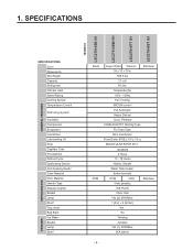
...it out ‚ . Check the amount that goes into the ice tray. (Refer to the Icemaker, follow these steps: • Lift the ice shelf as shown in the right figure and pull it ‚ . 5) When ice tray has finished rotation, water comes out the water tube. DISASSEMBLY ICEMAKER...it is small each time. Make sure it . The optimum amount is less than the optimum level. - 9 - DISASSEMBLY ICE STORAGE BIN 2) The bell rings (ding ~ dong), the ice tray rotates, and water comes out the icemaker water tube. Feeler Arm Test switch (On the lower part of icemaker) 2 1...
...it out ‚ . Check the amount that goes into the ice tray. (Refer to the Icemaker, follow these steps: • Lift the ice shelf as shown in the right figure and pull it ‚ . 5) When ice tray has finished rotation, water comes out the water tube. DISASSEMBLY ICEMAKER...it is small each time. Make sure it . The optimum amount is less than the optimum level. - 9 - DISASSEMBLY ICE STORAGE BIN 2) The bell rings (ding ~ dong), the ice tray rotates, and water comes out the icemaker water tube. Feeler Arm Test switch (On the lower part of icemaker) 2 1...

Owner's Manual
Page 11
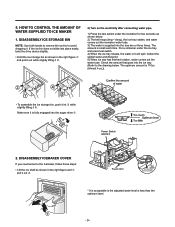
.... Otherwise the water may spill over. This happens when too much water is complete, check the level of water supplied is supplied into the ice tray. 4) If the ice cubes stick together, decrease the water supplying time. Switch ON ON Switch OFF 1 2 3. Caution: • Unplug the power cord from ...the wall outlet and wait at 9s when the refrigerator is supplied into the ice tray. When the adjustment of the control switch for the amount of water in the control panel. 3-2 Control the amount of water supplied, adjust step ...
.... Otherwise the water may spill over. This happens when too much water is complete, check the level of water supplied is supplied into the ice tray. 4) If the ice cubes stick together, decrease the water supplying time. Switch ON ON Switch OFF 1 2 3. Caution: • Unplug the power cord from ...the wall outlet and wait at 9s when the refrigerator is supplied into the ice tray. When the adjustment of the control switch for the amount of water in the control panel. 3-2 Control the amount of water supplied, adjust step ...
Owner's Manual
Page 15
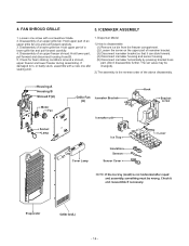
Loosen one afer sealing well. 1. Dispenser Model 1) How to disassemble: (1) Remove ice bin from the freezer compartment. (2) Loosen the screw on the upper part of an upper grille fan (U) and pull forward carefully. 3. ICEMAKER ... shroud, upper freezer and lower freezer during assembling. Housing A Housing B Shroud F(U) Motor Fan Socket Lamp Grille Fan Icemaker Bracket (U) Icemaker unit Cover Lamp Ice Tray Insulation Sensor Sensor Cover Hook Bracket screw Lever Evaporator - 14 - Disassembly of a lower grille fan: Hold upper part of the above disassembly. Disassembly of ...
Loosen one afer sealing well. 1. Dispenser Model 1) How to disassemble: (1) Remove ice bin from the freezer compartment. (2) Loosen the screw on the upper part of an upper grille fan (U) and pull forward carefully. 3. ICEMAKER ... shroud, upper freezer and lower freezer during assembling. Housing A Housing B Shroud F(U) Motor Fan Socket Lamp Grille Fan Icemaker Bracket (U) Icemaker unit Cover Lamp Ice Tray Insulation Sensor Sensor Cover Hook Bracket screw Lever Evaporator - 14 - Disassembly of a lower grille fan: Hold upper part of the above disassembly. Disassembly of ...
Owner's Manual
Page 57
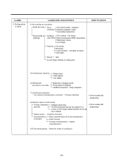
.... Small capacity. Faulty compressor. 7) Continuous operation - The EPS (styrofoam) drip tray has sediment in it. Charge of refrigerant. Fan is weak. Fan misuse. Not tightly connected. Ice and foreign materials on rotating parts. Low valtage. 6) Refrigerant too much or too... dump. • Check visually after disassembly. 8) Damper opens continuously. A screw or other foreign material has fallen into the drip tray or damper. Rating misuse. Damping evaporator contact. Fan misuse. Faulty fan. Bent. Fan shroud contact. - Insufficient motor RPM Fan ...
.... Small capacity. Faulty compressor. 7) Continuous operation - The EPS (styrofoam) drip tray has sediment in it. Charge of refrigerant. Fan is weak. Fan misuse. Not tightly connected. Ice and foreign materials on rotating parts. Low valtage. 6) Refrigerant too much or too... dump. • Check visually after disassembly. 8) Damper opens continuously. A screw or other foreign material has fallen into the drip tray or damper. Rating misuse. Damping evaporator contact. Fan misuse. Faulty fan. Bent. Fan shroud contact. - Insufficient motor RPM Fan ...

Owner's Manual
Page 59
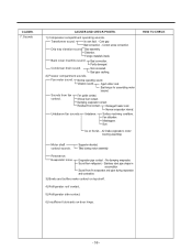
Condensation and ice formation. Condensation on the gasket surface. Liquid shortage. Bad wing adhesion. Too much notch. Condensation in the compressor compartment. Sounds 1) Compressor ...diameter of drain. No vibration damper. Condensation on the floor. Wing sag(lower part). Distorted. Aged. Not Compressor base not connected. Tray drip. Damping Bushing-S. Surface. Discharging hose Evaporation tray located at wrong place. Position of stopper). CLAIMS. 6. Duct door is cut . Liquid leak. location. Compressor sound inserted. Burnt...
Condensation and ice formation. Condensation on the gasket surface. Liquid shortage. Bad wing adhesion. Too much notch. Condensation in the compressor compartment. Sounds 1) Compressor ...diameter of drain. No vibration damper. Condensation on the floor. Wing sag(lower part). Distorted. Aged. Not Compressor base not connected. Tray drip. Damping Bushing-S. Surface. Discharging hose Evaporation tray located at wrong place. Position of stopper). CLAIMS. 6. Duct door is cut . Liquid leak. location. Compressor sound inserted. Burnt...
Owner's Manual
Page 60
... top shelf. 4) Refrigerator roof contact. 5) Refrigerator side contact. 6) Insufficient lubricants on the fan. - Stainless steel pipe shape in accumulator. Shroud burr contact. Ice on door hinge. - 59 - Drip tray vibration sound. Not connected. Correct screw connection. Evaporator noise. Sound from fin evaporator and pipe during motor assembly. Its own fault. - Bad connection...
... top shelf. 4) Refrigerator roof contact. 5) Refrigerator side contact. 6) Insufficient lubricants on the fan. - Stainless steel pipe shape in accumulator. Shroud burr contact. Ice on door hinge. - 59 - Drip tray vibration sound. Not connected. Correct screw connection. Evaporator noise. Sound from fin evaporator and pipe during motor assembly. Its own fault. - Bad connection...
Owner's Manual
Page 86
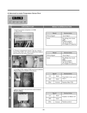
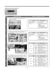
...in CON8 on Main PCB. 1 RESULT & SERVICE ACTION Result Firmly plugged Loose Service Action Go to Step 2 In Freezer compartment remove Tray ice, remove screw of Ice maker unit, quit Ice maker from holders and check for any loose connection. 2 Result Firmly plugged Loose Service Action Go to Step 3 In the Main PCB... shown in the picture. 3 Result 0 Ù Short OFF Open Other Normal Service Action Plug CON 8, then, go to Step 4 Replace Main PCB Unplug Ice maker unit and check value between White to White. 4 Result 0 Ù Short OFF Open Other Normal Service Action Replace...
...in CON8 on Main PCB. 1 RESULT & SERVICE ACTION Result Firmly plugged Loose Service Action Go to Step 2 In Freezer compartment remove Tray ice, remove screw of Ice maker unit, quit Ice maker from holders and check for any loose connection. 2 Result Firmly plugged Loose Service Action Go to Step 3 In the Main PCB... shown in the picture. 3 Result 0 Ù Short OFF Open Other Normal Service Action Plug CON 8, then, go to Step 4 Replace Main PCB Unplug Ice maker unit and check value between White to White. 4 Result 0 Ù Short OFF Open Other Normal Service Action Replace...
Owner's Manual
Page 88
...press again. 4 Result 5V ON 0V Other 5V OFF 0V Other Service Action Replace Ice maker unit Go to Step 5 Replace Main PCB Go to Step 5 Replace Ice maker unit Replace Main PCB - 87 - 8) Abnormal Ice maker Unit Error NO. CHECKING FLOW Remove Cover PCB, then check for any loose connection... in CON 8. 1 RESULT & SERVICE ACTION Result Firmly plugged Loose Service Action Go to Step 2 Remove Tray ice, remove screw of Ice maker unit for any loose connection. 2 Result Firmly plugged Loose Service Action Go to Step 3 Check Voltage from...
...press again. 4 Result 5V ON 0V Other 5V OFF 0V Other Service Action Replace Ice maker unit Go to Step 5 Replace Main PCB Go to Step 5 Replace Ice maker unit Replace Main PCB - 87 - 8) Abnormal Ice maker Unit Error NO. CHECKING FLOW Remove Cover PCB, then check for any loose connection... in CON 8. 1 RESULT & SERVICE ACTION Result Firmly plugged Loose Service Action Go to Step 2 Remove Tray ice, remove screw of Ice maker unit for any loose connection. 2 Result Firmly plugged Loose Service Action Go to Step 3 Check Voltage from...


