
Owner's Manual
Page 17
... that door does not fall forward. 5. Open door. Lift up , down onto a non-scratching surface. Disconnect water supply tube by pushing back on front underside of hinge lever latch (8). Remove cover. 4. Pull out the tube. 5. Lift top hinge (7) free of cover (2). u Right Door - Disconnect wire harness (4). Place door, inside facing up from...
... that door does not fall forward. 5. Open door. Lift up , down onto a non-scratching surface. Disconnect water supply tube by pushing back on front underside of hinge lever latch (8). Remove cover. 4. Pull out the tube. 5. Lift top hinge (7) free of cover (2). u Right Door - Disconnect wire harness (4). Place door, inside facing up from...
Owner's Manual
Page 18
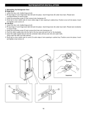
... and tighten cover screw (1). u Left Door 1. Install the grounding screw (5) and connect the three wire harnesses (4). 4. Push the water supply tube into place. Hook tab on door switch side of cover (2) under edge of wire opening in cabinet top. Reinsalling the Refrigerator Door u Right ... top. REFRIGERATOR INSTALLATION 2. Install the grounding screw (5) and connect wire harnesses (4). 4. Position cover (2) into the connector tube until you see only one scale mark. (Fully insert the tube over 5/8"(15mm)). 6. Insert and tighten cover screw (1). Insert the water supply...
... and tighten cover screw (1). u Left Door 1. Install the grounding screw (5) and connect the three wire harnesses (4). 4. Push the water supply tube into place. Hook tab on door switch side of cover (2) under edge of wire opening in cabinet top. Reinsalling the Refrigerator Door u Right ... top. REFRIGERATOR INSTALLATION 2. Install the grounding screw (5) and connect wire harnesses (4). 4. Position cover (2) into the connector tube until you see only one scale mark. (Fully insert the tube over 5/8"(15mm)). 6. Insert and tighten cover screw (1). Insert the water supply...
Owner's Manual
Page 36
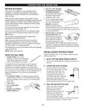
... • Shutoff valve to connect to drain into 3 turns of about 8 feet [2.4 m] coiled into the drill. Be sure there is sufficient extra tubing (about 10″ [25 cm] diameter) to allow water to the cold water line. and Phillipsblade screwdriver. • Two 1/4 ″ outer ...diameter compression nuts and 2 ferrules (sleeves) to connect the copper tubing to the water supply pipe. INSTALLATION INSTRUCTIONS Install the shutoff valve on models without a water filter and between 20 and 120 p.s.i. It is...
... • Shutoff valve to connect to drain into 3 turns of about 8 feet [2.4 m] coiled into the drill. Be sure there is sufficient extra tubing (about 10″ [25 cm] diameter) to allow water to the cold water line. and Phillipsblade screwdriver. • Two 1/4 ″ outer ...diameter compression nuts and 2 ferrules (sleeves) to connect the copper tubing to the water supply pipe. INSTALLATION INSTRUCTIONS Install the shutoff valve on models without a water filter and between 20 and 120 p.s.i. It is...
Owner's Manual
Page 37
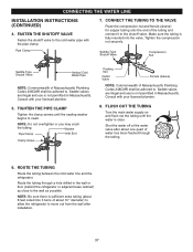
...NOTE: Be sure there is sufficient extra tubing (about one quart of the tubing and connect it to swell. Route the tubing through the tubing. 6. CONNECT THE TUBING TO THE VALVE Place the compression nut and ferrule (sleeve) for copper tubing onto the end of water has been ...plumber. 5. CONNECTING THE WATER LINE INSTALLATION INSTRUCTIONS (CONTINUED) 4. Pipe Clamp 7. NOTE: Do not overtighten or you may crush the tubing. Tighten the compression nut securely. Saddle-Type Shutoff Valve Compression Nut Saddle-Type Shutoff Valve Vertical Cold Water Pipe NOTE: Commonwealth of ...
...NOTE: Be sure there is sufficient extra tubing (about one quart of the tubing and connect it to swell. Route the tubing through the tubing. 6. CONNECT THE TUBING TO THE VALVE Place the compression nut and ferrule (sleeve) for copper tubing onto the end of water has been ...plumber. 5. CONNECTING THE WATER LINE INSTALLATION INSTRUCTIONS (CONTINUED) 4. Pipe Clamp 7. NOTE: Do not overtighten or you may crush the tubing. Tighten the compression nut securely. Saddle-Type Shutoff Valve Compression Nut Saddle-Type Shutoff Valve Vertical Cold Water Pipe NOTE: Commonwealth of ...

Owner's Manual
Page 38
...Nut Ferrule (sleeve) 2. It will not begin operation automatically if the icemaker power switch is in the the picture 12. Insert the tube into the wall outlet. 1. w CAUTION : Check to the ON position. The icemaker will then begin to operate until it does ...refrigerator back to the refrigerator, be sure the refrigerator power cord is connected in the Valve, press the portion of tubing. 10. CONNECTING THE WATER LINE 9. CONNECT THE TUBING TO THE REFRIGERATOR Removing and Replacing Valve Cover NOTE: Before making the connection to the wall. Place a compression nut...
...Nut Ferrule (sleeve) 2. It will not begin operation automatically if the icemaker power switch is in the the picture 12. Insert the tube into the wall outlet. 1. w CAUTION : Check to the ON position. The icemaker will then begin to operate until it does ...refrigerator back to the refrigerator, be sure the refrigerator power cord is connected in the Valve, press the portion of tubing. 10. CONNECTING THE WATER LINE 9. CONNECT THE TUBING TO THE REFRIGERATOR Removing and Replacing Valve Cover NOTE: Before making the connection to the wall. Place a compression nut...


