
Owners Manual
Page 2
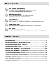
...PART6. INITIAL STEPS FOR INSTALLING YOUR DRYER 7-12 PART4. ACCESSORIES INSTALLATION ...13-14 PART5. TABLE OF CONTENTS PART1. TROUBLESHOOTING GUIDE ...29-31 LG DRYER LIMITED WARRANTY ...32 2 SPECIFICATIONS ...3 PART2. OPERATING YOUR DRYER...23-28 PART10. GAS REQUIREMENTS AND INSTRUCTIONS 20 PART8. PRODUCT FEATURES 1...you can benefit from good time efficiency, quiet operation and energy saving system. 2 STAINLESS STEEL DRUM Stainless steel drum doesn't have any rust by nature so that rust-free drum keeps clothes away from stain all time. 3 ARTISTIC DESIGN Modern front panel look and big ...
...PART6. INITIAL STEPS FOR INSTALLING YOUR DRYER 7-12 PART4. ACCESSORIES INSTALLATION ...13-14 PART5. TABLE OF CONTENTS PART1. TROUBLESHOOTING GUIDE ...29-31 LG DRYER LIMITED WARRANTY ...32 2 SPECIFICATIONS ...3 PART2. OPERATING YOUR DRYER...23-28 PART10. GAS REQUIREMENTS AND INSTRUCTIONS 20 PART8. PRODUCT FEATURES 1...you can benefit from good time efficiency, quiet operation and energy saving system. 2 STAINLESS STEEL DRUM Stainless steel drum doesn't have any rust by nature so that rust-free drum keeps clothes away from stain all time. 3 ARTISTIC DESIGN Modern front panel look and big ...
Owners Manual
Page 5
... the appliance is moving. 6) Do not install or store this appliance where it will not fit the outlet, have come into the appliance if the drum is properly grounded. SAVE THESE INSTRUCTIONS GROUNDING INSTRUCTIONS This appliance must be grounded. Do not modify the plug provided with a cord having an equipment-grounding...
... the appliance is moving. 6) Do not install or store this appliance where it will not fit the outlet, have come into the appliance if the drum is properly grounded. SAVE THESE INSTRUCTIONS GROUNDING INSTRUCTIONS This appliance must be grounded. Do not modify the plug provided with a cord having an equipment-grounding...
Owners Manual
Page 11
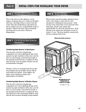
...exceed 0.6 inches (1.5 cm). The exhaust air or the exhaust pipe should be checked with the dryer running with damp clothes to the dryer drum/drying compartment and, after approximately two minutes. Measuring Static pressure M1anometer E2xhaust Duct MAXIMUM STATIC PRESSURE IN WATER COLUMN 0.6 inche (1.5 cm) ...and the main burner will re-attempt gas ignition after completing all steps in this manual for three minutes. Prior to the dryer drum/drying compartment and, after the dryer has been operating for proper installation of detergent and water, with no load. Static pressure ...
...exceed 0.6 inches (1.5 cm). The exhaust air or the exhaust pipe should be checked with the dryer running with damp clothes to the dryer drum/drying compartment and, after approximately two minutes. Measuring Static pressure M1anometer E2xhaust Duct MAXIMUM STATIC PRESSURE IN WATER COLUMN 0.6 inche (1.5 cm) ...and the main burner will re-attempt gas ignition after completing all steps in this manual for three minutes. Prior to the dryer drum/drying compartment and, after the dryer has been operating for proper installation of detergent and water, with no load. Static pressure ...
Owners Manual
Page 22
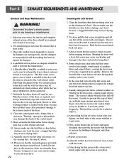
.... 5. Always make sure the lint filter is placed in hard to remove. Remove lint from the lint screen before running the dryer. Ordinarily, the dryer drum will need no care. Label all wires prior to disconnection when servicing the dryer, because wiring errors can be used to exhaust the dryer when...
.... 5. Always make sure the lint filter is placed in hard to remove. Remove lint from the lint screen before running the dryer. Ordinarily, the dryer drum will need no care. Label all wires prior to disconnection when servicing the dryer, because wiring errors can be used to exhaust the dryer when...
Owners Manual
Page 27
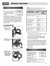
...; Start the dryer. 10. Anti Bacterial This option can only be dried on delicate fabrics. 27 The RACK DRY is evenly placed right onto the drum inside the dryer to match the fabrics in your load by using the Air Dry temperature setting. Hold the dryer rack with the HEAVY DUTY.... Items containing foam, rubber, or plastic must be used with both hands. 2. This option reduces certain types of bacteria. Put the dryer rack into the drum 3. Low/Ultra 20/30 Low Air Dry/ 50/30 Ultra Low Foam rubber pillows Air Dry 50 Athletic shoes Air Dry 20 * Reset time as...
...; Start the dryer. 10. Anti Bacterial This option can only be dried on delicate fabrics. 27 The RACK DRY is evenly placed right onto the drum inside the dryer to match the fabrics in your load by using the Air Dry temperature setting. Hold the dryer rack with the HEAVY DUTY.... Items containing foam, rubber, or plastic must be used with both hands. 2. This option reduces certain types of bacteria. Put the dryer rack into the drum 3. Low/Ultra 20/30 Low Air Dry/ 50/30 Ultra Low Foam rubber pillows Air Dry 50 Athletic shoes Air Dry 20 * Reset time as...
Owners Manual
Page 29
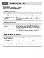
... Question What to dry only clean items, because dirty items can soil clean clothes placed in the same load or later placed in the dryer drum. • Were your dryer to Do • Is the fuse blown, or is blown or the circuit breaker tripped, the dryer might tumble but not...
... Question What to dry only clean items, because dirty items can soil clean clothes placed in the same load or later placed in the dryer drum. • Were your dryer to Do • Is the fuse blown, or is blown or the circuit breaker tripped, the dryer might tumble but not...
Service Manual
Page 3
...TEST 7 GAS VALVE TEST - EXPLODED VIEW ...37 12-1. CABINET & DOOR ASSEMBLY 38 12-3-1. INSTALLATION INSTRUCTIONS 6 4. TEST 4 MOISTURE SENSOR 24 9-5. DRUM & MOTOR ASSEMBLY : GAS TYPE 40 13. OUT ...18 8. MEASURE WITH POWER OFF 22 9-3. ELECTRIC TYPE 26 9-7. DISASSEMBLY INSTRUCTIONS 30 12. ...REPLACEMENT PARTS LIST 41 3 SPECIFICATIONS ...4 2. DRUM & MOTOR ASSEMBLY : ELECTRIC TYPE 39 12-3-2. TEST 5 DOOR SWITCH TEST 25 9-6. CHANGE GAS SETTING (NATURAL GAS, PROPANE GAS 28 11...
...TEST 7 GAS VALVE TEST - EXPLODED VIEW ...37 12-1. CABINET & DOOR ASSEMBLY 38 12-3-1. INSTALLATION INSTRUCTIONS 6 4. TEST 4 MOISTURE SENSOR 24 9-5. DRUM & MOTOR ASSEMBLY : GAS TYPE 40 13. OUT ...18 8. MEASURE WITH POWER OFF 22 9-3. ELECTRIC TYPE 26 9-7. DISASSEMBLY INSTRUCTIONS 30 12. ...REPLACEMENT PARTS LIST 41 3 SPECIFICATIONS ...4 2. DRUM & MOTOR ASSEMBLY : ELECTRIC TYPE 39 12-3-2. TEST 5 DOOR SWITCH TEST 25 9-6. CHANGE GAS SETTING (NATURAL GAS, PROPANE GAS 28 11...

Service Manual
Page 5
... 5 5 No. of Programs 9 7 No. of Dry Levels 5 5 Sound levels High / Low / Off Sensor Moisture Temperature Avaiable Avaiable Electrode sensor Termistor Reversible Door Avaiable Drum Stainless Steel Dryer Rack Child Lock Avaiable Avaiable Interior Light Product (WxHxD) Packing (WxHxD) Avaiable 27" x 42 3/4 x 28 1/3 29 1/2" x 44 3/4 x 30 3/4 5...15 W (125mA) AC 120V AC 240V (ELECTRIC TYPE) AC 120V GAS VALVE CONTROL TYPE 13 W (110mA) x 2 Electronic AC 120V(GAS TYPE) DRUM CAPACITY 7.3 cu.ft. Weight (lbs) : Net / Gross 124 / 144 No. of Dry Options 5 5 No.
... 5 5 No. of Programs 9 7 No. of Dry Levels 5 5 Sound levels High / Low / Off Sensor Moisture Temperature Avaiable Avaiable Electrode sensor Termistor Reversible Door Avaiable Drum Stainless Steel Dryer Rack Child Lock Avaiable Avaiable Interior Light Product (WxHxD) Packing (WxHxD) Avaiable 27" x 42 3/4 x 28 1/3 29 1/2" x 44 3/4 x 30 3/4 5...15 W (125mA) AC 120V AC 240V (ELECTRIC TYPE) AC 120V GAS VALVE CONTROL TYPE 13 W (110mA) x 2 Electronic AC 120V(GAS TYPE) DRUM CAPACITY 7.3 cu.ft. Weight (lbs) : Net / Gross 124 / 144 No. of Dry Options 5 5 No.

Service Manual
Page 6
2 FEATURES AND BENEFITS DLE5977W/DLG5988W/DLE5977B/DLG5988B DLE3777W/DLG3788W 3 INSTALLATION INSTRUCTIONS Dryer Rack Installation Instructions 1Open the door. Hold the dryer rack with both hands. 2 Put the dryer rack into the drum 3 Make sure that dryer is evenly placed right onto the drum inside and door rim. 6
2 FEATURES AND BENEFITS DLE5977W/DLG5988W/DLE5977B/DLG5988B DLE3777W/DLG3788W 3 INSTALLATION INSTRUCTIONS Dryer Rack Installation Instructions 1Open the door. Hold the dryer rack with both hands. 2 Put the dryer rack into the drum 3 Make sure that dryer is evenly placed right onto the drum inside and door rim. 6

Service Manual
Page 20
... 6 20 The display number is open the door. Current Temp. (5 ~ 70) ELECTRIC TYPE : Heater runs GAS TYPE : GAS Valve runs (Display the Temperature of Inside drum.) Gas valve See test 7 4 times Control Off During check, Motor & Heater Off + Lamp On + If the door is below 180, in the end. Pressing the...
... 6 20 The display number is open the door. Current Temp. (5 ~ 70) ELECTRIC TYPE : Heater runs GAS TYPE : GAS Valve runs (Display the Temperature of Inside drum.) Gas valve See test 7 4 times Control Off During check, Motor & Heater Off + Lamp On + If the door is below 180, in the end. Pressing the...

Service Manual
Page 23
...between Connector "WH3- " (Brown wire)? NO Is resistance below 3Ω between terminals of Power cord with earth line.) Trouble Symptom Drum will not rotate; Test 3 Motor test Caution Before measuring resistance, be sure to turn Power off from • Motor Pulley. ...Check Controller connector. • Replace Outlet • Thermostat. (Refer to 'Component') • Check Idler Assembly. • Drum Belt cuts off • Drum Belt takes off , and do voltage discharge. (When discharging, contact the metal plug of Outlet Thermostat attached to Motor Bracket ...
...between Connector "WH3- " (Brown wire)? NO Is resistance below 3Ω between terminals of Power cord with earth line.) Trouble Symptom Drum will not rotate; Test 3 Motor test Caution Before measuring resistance, be sure to turn Power off from • Motor Pulley. ...Check Controller connector. • Replace Outlet • Thermostat. (Refer to 'Component') • Check Idler Assembly. • Drum Belt cuts off • Drum Belt takes off , and do voltage discharge. (When discharging, contact the metal plug of Outlet Thermostat attached to Motor Bracket ...

Service Manual
Page 25
.... Measure while Door is open . YES • Door switch Check (Refer to Component testing.) • Check Lamp. (When opening Door, Drum motor and Trouble Symptom Heater run continuously; " (White wire) after NO taking Connector WH3, BL2 out from Controller. YES • Door switch...Door is closed . Door Close is 300~60Ω between "WH3- " (White wire) and "RD3- Check if resistance is not sensed. (Drum motor will flash at 0.5 second intervals.) Measurement Condition After turning Dryer Power Off, measure resistance. " (Black wire) NO Connector WH3, RD3 after...
.... Measure while Door is open . YES • Door switch Check (Refer to Component testing.) • Check Lamp. (When opening Door, Drum motor and Trouble Symptom Heater run continuously; " (White wire) after NO taking Connector WH3, BL2 out from Controller. YES • Door switch...Door is closed . Door Close is 300~60Ω between "WH3- " (White wire) and "RD3- Check if resistance is not sensed. (Drum motor will flash at 0.5 second intervals.) Measurement Condition After turning Dryer Power Off, measure resistance. " (Black wire) NO Connector WH3, RD3 after...

Service Manual
Page 33
... shield in place. 3. Remove 4 screws. 5. Remove the bulb and replace with a 15 watt, 120 volt candelabra-base bulb. 5. Carefully remove Drum out. 1. Disassemble the top plate. 2. Disassemble the Tub Drum [Front]. -1 1. 1. Disassemble the door. 2. Slide the shield up and remove. 4. Replace the lamp shield and screw. 33 Loosen belt from motor and...
... shield in place. 3. Remove 4 screws. 5. Remove the bulb and replace with a 15 watt, 120 volt candelabra-base bulb. 5. Carefully remove Drum out. 1. Disassemble the top plate. 2. Disassemble the Tub Drum [Front]. -1 1. 1. Disassemble the door. 2. Slide the shield up and remove. 4. Replace the lamp shield and screw. 33 Loosen belt from motor and...

Service Manual
Page 35
Remove the Drum assembly. 4. Disassemble the top plate. 2. Remove the Cabinet Cover and Tub Drum [Front]. 3. Remove the Drum assembly. 4. 1. Disconnect electrode sensor. 1. Remove the Tub Drum [Rear] towards the front. 35 Remove the fan. 7. Remove the Cabinet Cover and Tub Drum [Front]. 3. Disconnect the motor clamp and motor. 1. Remove 7 screws. 5. Remove 3 screws. 3. Remove the bolt and washer. 6. Remove the filter. 2. Remove Cover Gride. 4. Disassembly the top plate. 2. Remove 2 screws and cover(Air guide). 5.
Remove the Drum assembly. 4. Disassemble the top plate. 2. Remove the Cabinet Cover and Tub Drum [Front]. 3. Remove the Drum assembly. 4. 1. Disconnect electrode sensor. 1. Remove the Tub Drum [Rear] towards the front. 35 Remove the fan. 7. Remove the Cabinet Cover and Tub Drum [Front]. 3. Disconnect the motor clamp and motor. 1. Remove 7 screws. 5. Remove 3 screws. 3. Remove the bolt and washer. 6. Remove the filter. 2. Remove Cover Gride. 4. Disassembly the top plate. 2. Remove 2 screws and cover(Air guide). 5.

Service Manual
Page 36
Remove the Cover Cabinet. 3. Disconnect Air duct from the Tub Drum [Front] and Tub Drum [Rear]. 36 Remove the air duct. 1. Remove the Drum assembly and Tub Drum [Rear]. 4. Remove the Cover Cabinet and Tub Drum [Front]. 3. Remove the roller from the Tub Drum [Front]. 5. Disassemble the top plate. 2. Disassemble the top plate. 2. Remove filter and 2 screws. 4. 1.
Remove the Cover Cabinet. 3. Disconnect Air duct from the Tub Drum [Front] and Tub Drum [Rear]. 36 Remove the air duct. 1. Remove the Drum assembly and Tub Drum [Rear]. 4. Remove the Cover Cabinet and Tub Drum [Front]. 3. Remove the roller from the Tub Drum [Front]. 5. Disassemble the top plate. 2. Disassemble the top plate. 2. Remove filter and 2 screws. 4. 1.

Service Manual
Page 39
Drum & Motor Assembly : Electric Type F200 K400 K120 K140 K100 K130 K250 K310 K330 K320 K340 K222 K221 K620 K210 K250 K550 K560 K610 K240 F130 F110 F120 K530 F140 K640 K600 K510 K520 K650 39 12-3-1.
Drum & Motor Assembly : Electric Type F200 K400 K120 K140 K100 K130 K250 K310 K330 K320 K340 K222 K221 K620 K210 K250 K550 K560 K610 K240 F130 F110 F120 K530 F140 K640 K600 K510 K520 K650 39 12-3-1.
Service Manual
Page 41
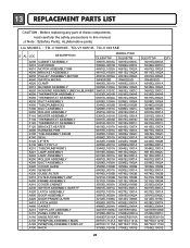
...HOUSING ASSEMBLY (MECH),BLOWER 3661EL1001C 3661EL1001C K550 THERMISTOR ASSEMBLY 6323EL2001B 6323EL2001B K560 THERMOSTAT ASSEMBLY 6931EL3002A 6931EL3002A K530 DUCT ASSEMBLY 5209EL1006A 5209EL1006A K400 TUB,DRUM[BACK] 3044EL0002B 3044EL0002B F200 DUCT ASSEMBLY 5209EL1001C 5209EL1001C K250 ROLLER ASSEMBLY 4581EL3001A 4581EL3001A F110 HEATER ASSEMBLY 5301EL1001A 5301EL1001A F130 THERMOSTAT ASSEMBLY 6931EL3003D ... any part of these components, read carefully the safety precautions in this manual. ¡Æ Note : S(Safety Parts), AL(Alternative parts) LG MODEL : TD-V10050E.
...HOUSING ASSEMBLY (MECH),BLOWER 3661EL1001C 3661EL1001C K550 THERMISTOR ASSEMBLY 6323EL2001B 6323EL2001B K560 THERMOSTAT ASSEMBLY 6931EL3002A 6931EL3002A K530 DUCT ASSEMBLY 5209EL1006A 5209EL1006A K400 TUB,DRUM[BACK] 3044EL0002B 3044EL0002B F200 DUCT ASSEMBLY 5209EL1001C 5209EL1001C K250 ROLLER ASSEMBLY 4581EL3001A 4581EL3001A F110 HEATER ASSEMBLY 5301EL1001A 5301EL1001A F130 THERMOSTAT ASSEMBLY 6931EL3003D ... any part of these components, read carefully the safety precautions in this manual. ¡Æ Note : S(Safety Parts), AL(Alternative parts) LG MODEL : TD-V10050E.
Service Manual
Page 42
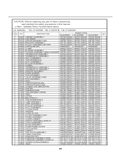
..., read carefully the safety precautions in this manual. ¡Æ Note : S(Safety Parts), AL(Alternative parts) LG MODEL : TD-V10050E. TD-V10051E, TD-V10055E S AL LOC DESCRIPTION DLG5988W MODEL P/NO DLG5988B DLG3788W QTY A500...ASSEMBLY 6323EL2001B 6323EL2001B 6323EL2001B 1 K560 THERMOSTAT ASSEMBLY 6931EL3002A 6931EL3002A 6931EL3002A 1 K530 DUCT ASSEMBLY 5209EL1006A 5209EL1006A 5209EL1006A 1 K400 TUB,DRUM[BACK] 3044EL0002B 3044EL0002B 3044EL0002B 1 F200 DUCT ASSEMBLY 5209EL1001D 5209EL1001D 5209EL1001D 1 K250 ROLLER ASSEMBLY 4581EL3001A 4581EL3001A 4581EL3001A 1 M210...
..., read carefully the safety precautions in this manual. ¡Æ Note : S(Safety Parts), AL(Alternative parts) LG MODEL : TD-V10050E. TD-V10051E, TD-V10055E S AL LOC DESCRIPTION DLG5988W MODEL P/NO DLG5988B DLG3788W QTY A500...ASSEMBLY 6323EL2001B 6323EL2001B 6323EL2001B 1 K560 THERMOSTAT ASSEMBLY 6931EL3002A 6931EL3002A 6931EL3002A 1 K530 DUCT ASSEMBLY 5209EL1006A 5209EL1006A 5209EL1006A 1 K400 TUB,DRUM[BACK] 3044EL0002B 3044EL0002B 3044EL0002B 1 F200 DUCT ASSEMBLY 5209EL1001D 5209EL1001D 5209EL1001D 1 K250 ROLLER ASSEMBLY 4581EL3001A 4581EL3001A 4581EL3001A 1 M210...


