

Service Manual
Page 14
...± 9°F (125 ± 5°C) Close at 149 ± 9°F (65 ± 5°C) Same shape as Outlet Thermostat. Measure resistance of terminal to Open condition. Idler switch Measure resistance of terminal Resistance value : to terminal 80Ω ~ 100Ω ...; Blow housing Safety • Electric type 5. lever open must • Heater case- Hi limit Thermostat (Auto reset) 3. Lever push (close) Resistance value ∞ 14 5 COMPONENT TESTING INFORMATION ! Outlet Thermostat ( Auto reset) • Check Top Marking : N85 4. Resistance value ∞ Resistance value <...
...± 9°F (125 ± 5°C) Close at 149 ± 9°F (65 ± 5°C) Same shape as Outlet Thermostat. Measure resistance of terminal to Open condition. Idler switch Measure resistance of terminal Resistance value : to terminal 80Ω ~ 100Ω ...; Blow housing Safety • Electric type 5. lever open must • Heater case- Hi limit Thermostat (Auto reset) 3. Lever push (close) Resistance value ∞ 14 5 COMPONENT TESTING INFORMATION ! Outlet Thermostat ( Auto reset) • Check Top Marking : N85 4. Resistance value ∞ Resistance value <...

Service Manual
Page 16
Outlet Thermostat (Manual reset) • Check Top Marking : N100 Test Procedure Measure resistance of terminal to terminal Open at 203 ± 7°F (95 ± 5°C) Close at ... ± 7°C) Manual reset If thermal fuse is open must be replaced Resistance value ∞ Continuity < 1Ω • Gas type • Gas funnel 16 Outlet Thermostat (Auto reset) • Check Top Marking : N95 13. Component 13.
Outlet Thermostat (Manual reset) • Check Top Marking : N100 Test Procedure Measure resistance of terminal to terminal Open at 203 ± 7°F (95 ± 5°C) Close at ... ± 7°C) Manual reset If thermal fuse is open must be replaced Resistance value ∞ Continuity < 1Ω • Gas type • Gas funnel 16 Outlet Thermostat (Auto reset) • Check Top Marking : N95 13. Component 13.

Service Manual
Page 20
... This TEST should be in Standby (unit plugged in, display off in normal condition. Activating the Heater manually with the Door open may trip the Thermostat attached to the Heater, therefore do not activate it manually. (Do not press the door switch to the step 4. • Press Start 3 times and then...
... This TEST should be in Standby (unit plugged in, display off in normal condition. Activating the Heater manually with the Door open may trip the Thermostat attached to the Heater, therefore do not activate it manually. (Do not press the door switch to the step 4. • Press Start 3 times and then...

Service Manual
Page 23
.... • Check Door Switch. • Check Harness connection. " (Brown wire)? NO YES • Replace Control. (Relay check) • Check Controller connector. • Replace Outlet • Thermostat. (Refer to 'Component') • Check Idler Assembly. • Drum Belt cuts off • Drum Belt takes off , and do voltage discharge. (When discharging, contact the...
.... • Check Door Switch. • Check Harness connection. " (Brown wire)? NO YES • Replace Control. (Relay check) • Check Controller connector. • Replace Outlet • Thermostat. (Refer to 'Component') • Check Idler Assembly. • Drum Belt cuts off • Drum Belt takes off , and do voltage discharge. (When discharging, contact the...
Service Manual
Page 26
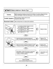
...off , and do voltage discharge. (When discharging, contact the metal plug of measured resistance is below 1Ω between terminal TH2 (Safety Thermostat). Test 6 Heater switch test - Electric Type Caution Before measuring resistance, be sure to turn Power off , measure the resistance. YES ...Check Controller. Is resistance between Heater terminal and below 1Ω between terminal TH3 (HI-Limit Thermostat). Check if the value of measured resistance is below 1Ω between Heater terminal and below 18 ~ 22Ω? 3. Check Motor. ...
...off , and do voltage discharge. (When discharging, contact the metal plug of measured resistance is below 1Ω between terminal TH2 (Safety Thermostat). Test 6 Heater switch test - Electric Type Caution Before measuring resistance, be sure to turn Power off , measure the resistance. YES ...Check Controller. Is resistance between Heater terminal and below 1Ω between terminal TH3 (HI-Limit Thermostat). Check if the value of measured resistance is below 1Ω between Heater terminal and below 18 ~ 22Ω? 3. Check Motor. ...

Service Manual
Page 27
... is more than AC 90V? Gas Type Caution When measuring power, be sure to wear insulated gloves, to avoid electric shock. YES NO • Check thermostat Hi limit Safety Igniter operates? (after Off ) YES • Change Valve NO • Harness check • Controller change 27 Trouble Symptom While operating, Heating will...
... is more than AC 90V? Gas Type Caution When measuring power, be sure to wear insulated gloves, to avoid electric shock. YES NO • Check thermostat Hi limit Safety Igniter operates? (after Off ) YES • Change Valve NO • Harness check • Controller change 27 Trouble Symptom While operating, Heating will...
Service Manual
Page 41
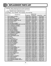
... components, read carefully the safety precautions in this manual. ¡Æ Note : S(Safety Parts), AL(Alternative parts) LG MODEL : TD-V10050E. TD-V10051E, TD-V10055E S AL LOC DESCRIPTION MODEL P/NO DLE5977W DLE5977B A500 CABINET ASSEMBLY 3091EL0003A... DUCT ASSEMBLY 5209EL1001C 5209EL1001C K250 ROLLER ASSEMBLY 4581EL3001A 4581EL3001A F110 HEATER ASSEMBLY 5301EL1001A 5301EL1001A F130 THERMOSTAT ASSEMBLY 6931EL3003D 6931EL3003D F140 THERMOSTAT ASSEMBLY 6931EL3001C 6931EL3001C F120 BRACKET,HEATER 4810EL1007A 4810EL1007A A600 HARNESS,PWB 6877EL1007A 6877EL1007A K100 TUB ...
... components, read carefully the safety precautions in this manual. ¡Æ Note : S(Safety Parts), AL(Alternative parts) LG MODEL : TD-V10050E. TD-V10051E, TD-V10055E S AL LOC DESCRIPTION MODEL P/NO DLE5977W DLE5977B A500 CABINET ASSEMBLY 3091EL0003A... DUCT ASSEMBLY 5209EL1001C 5209EL1001C K250 ROLLER ASSEMBLY 4581EL3001A 4581EL3001A F110 HEATER ASSEMBLY 5301EL1001A 5301EL1001A F130 THERMOSTAT ASSEMBLY 6931EL3003D 6931EL3003D F140 THERMOSTAT ASSEMBLY 6931EL3001C 6931EL3001C F120 BRACKET,HEATER 4810EL1007A 4810EL1007A A600 HARNESS,PWB 6877EL1007A 6877EL1007A K100 TUB ...
Service Manual
Page 42
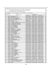
... 2 K510 BLOWER ASSEMBLY 5835EL1002A 5835EL1002A 5835EL1002A 1 K520 HOUSING ASSEMBLY (MECH),BLOWER 3661EL1001C 3661EL1001C 3661EL1001C 1 K550 THERMISTOR ASSEMBLY 6323EL2001B 6323EL2001B 6323EL2001B 1 K560 THERMOSTAT ASSEMBLY 6931EL3002A 6931EL3002A 6931EL3002A 1 K530 DUCT ASSEMBLY 5209EL1006A 5209EL1006A 5209EL1006A 1 K400 TUB,DRUM[BACK] 3044EL0002B 3044EL0002B 3044EL0002B 1 F200 DUCT ASSEMBLY 5209EL1001D 5209EL1001D ... of these components, read carefully the safety precautions in this manual. ¡Æ Note : S(Safety Parts), AL(Alternative parts) LG MODEL : TD-V10050E.
... 2 K510 BLOWER ASSEMBLY 5835EL1002A 5835EL1002A 5835EL1002A 1 K520 HOUSING ASSEMBLY (MECH),BLOWER 3661EL1001C 3661EL1001C 3661EL1001C 1 K550 THERMISTOR ASSEMBLY 6323EL2001B 6323EL2001B 6323EL2001B 1 K560 THERMOSTAT ASSEMBLY 6931EL3002A 6931EL3002A 6931EL3002A 1 K530 DUCT ASSEMBLY 5209EL1006A 5209EL1006A 5209EL1006A 1 K400 TUB,DRUM[BACK] 3044EL0002B 3044EL0002B 3044EL0002B 1 F200 DUCT ASSEMBLY 5209EL1001D 5209EL1001D ... of these components, read carefully the safety precautions in this manual. ¡Æ Note : S(Safety Parts), AL(Alternative parts) LG MODEL : TD-V10050E.


