
Service Manual
Page 3
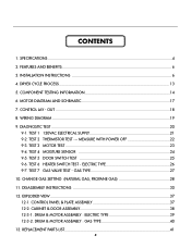
CONTENTS 1. DRYER CYCLE PROCESS ...13 5. TEST 1 120VAC ELECTRICAL SUPPLY 21 9-2. TEST 2 THERMISTOR TEST --- TEST 3 MOTOR TEST 23 9-4. CABINET & DOOR ASSEMBLY 38 12-3-1. REPLACEMENT PARTS LIST 41 3 COMPONENT TESTING INFORMATION 14 6. TEST 5 DOOR SWITCH TEST 25 ... PANEL & PLATE ASSEMBLY 37 12-2. INSTALLATION INSTRUCTIONS 6 4. WIRING DIAGRAM ...19 9. TEST 4 MOISTURE SENSOR 24 9-5. TEST 6 HEATER SWITCH TEST - MOTOR DIAGRAM AND SCHEMATIC 17 7. OUT ...18 8. DISASSEMBLY INSTRUCTIONS 30 12. CHANGE GAS SETTING (NATURAL GAS, PROPANE GAS 28 11. DRUM...
CONTENTS 1. DRYER CYCLE PROCESS ...13 5. TEST 1 120VAC ELECTRICAL SUPPLY 21 9-2. TEST 2 THERMISTOR TEST --- TEST 3 MOTOR TEST 23 9-4. CABINET & DOOR ASSEMBLY 38 12-3-1. REPLACEMENT PARTS LIST 41 3 COMPONENT TESTING INFORMATION 14 6. TEST 5 DOOR SWITCH TEST 25 ... PANEL & PLATE ASSEMBLY 37 12-2. INSTALLATION INSTRUCTIONS 6 4. WIRING DIAGRAM ...19 9. TEST 4 MOISTURE SENSOR 24 9-5. TEST 6 HEATER SWITCH TEST - MOTOR DIAGRAM AND SCHEMATIC 17 7. OUT ...18 8. DISASSEMBLY INSTRUCTIONS 30 12. CHANGE GAS SETTING (NATURAL GAS, PROPANE GAS 28 11. DRUM...

Service Manual
Page 5
of Dry Levels 5 5 Sound levels High / Low / Off Sensor Moisture Temperature Avaiable Avaiable Electrode sensor Termistor Reversible Door Avaiable Drum Stainless Steel Dryer Rack Child Lock Avaiable Avaiable Interior Light Product (WxHxD) Packing (WxHxD) Avaiable 27" x 42 3/4 x 28 1/3 29 1/2" x 44 3/4 x 30 3/4 5...Door Trim Blue White Black Porcelain Chromate + STS Deco Blue White Painted Blue White POWER SUPPLY 120V / 240V 60Hz (26A) ELECTRICITY CONSUMPTION MOTOR HEATER LAMP 250W (4.5A) 5400W (22.5A) 15 W (125mA) AC 120V AC 240V (ELECTRIC TYPE) AC 120V GAS VALVE ...
of Dry Levels 5 5 Sound levels High / Low / Off Sensor Moisture Temperature Avaiable Avaiable Electrode sensor Termistor Reversible Door Avaiable Drum Stainless Steel Dryer Rack Child Lock Avaiable Avaiable Interior Light Product (WxHxD) Packing (WxHxD) Avaiable 27" x 42 3/4 x 28 1/3 29 1/2" x 44 3/4 x 30 3/4 5...Door Trim Blue White Black Porcelain Chromate + STS Deco Blue White Painted Blue White POWER SUPPLY 120V / 240V 60Hz (26A) ELECTRICITY CONSUMPTION MOTOR HEATER LAMP 250W (4.5A) 5400W (22.5A) 15 W (125mA) AC 120V AC 240V (ELECTRIC TYPE) AC 120V GAS VALVE ...

Service Manual
Page 13
Dry Display erature Level time Electro- Default settings can be adjusted by users. Temp- 4 DRYER CYCLE PROCESS Cycle Default Conditions of operation and termination Drying Cooling Wrinkle care Temp- Default Tempsensor Control time Control** Time HEAVY DUTY...FRESHEN UP Dry ** (MID HIGH) - 20min Saturation (66±5°C) (5min) (47±5°C) 3Hr AIR DRY - - 30min Saturation No heater N/A N/A Load Motor Heater Off Time: 6min On Time: 10sec Temperature Control for each cycle * Sensor dry : "Dry Level" is set by users. ** Manual dry : "Temperature control" ...
Dry Display erature Level time Electro- Default settings can be adjusted by users. Temp- 4 DRYER CYCLE PROCESS Cycle Default Conditions of operation and termination Drying Cooling Wrinkle care Temp- Default Tempsensor Control time Control** Time HEAVY DUTY...FRESHEN UP Dry ** (MID HIGH) - 20min Saturation (66±5°C) (5min) (47±5°C) 3Hr AIR DRY - - 30min Saturation No heater N/A N/A Load Motor Heater Off Time: 6min On Time: 10sec Temperature Control for each cycle * Sensor dry : "Dry Level" is set by users. ** Manual dry : "Temperature control" ...

Service Manual
Page 23
...contacted. 23 Measurement Condition Turn the Dryer's Power Off, then measure resistance. Test 3 Motor test Caution Before measuring resistance, be sure to turn Power off from • Motor Pulley. • Replace Idler Switch. • Check Motor.(Refer to Motor Bracket operate Level by drum belt?... Switch. • Check Harness connection. " (White wire) and "BL2- " (Brown wire)? NO YES Does Idle Switch attached to 'Motor Diagram & Check') • Check if Control Connector is normal.) Is resistance below 3Ω between terminals of Power cord with earth line.) ...
...contacted. 23 Measurement Condition Turn the Dryer's Power Off, then measure resistance. Test 3 Motor test Caution Before measuring resistance, be sure to turn Power off from • Motor Pulley. • Replace Idler Switch. • Check Motor.(Refer to Motor Bracket operate Level by drum belt?... Switch. • Check Harness connection. " (White wire) and "BL2- " (Brown wire)? NO YES Does Idle Switch attached to 'Motor Diagram & Check') • Check if Control Connector is normal.) Is resistance below 3Ω between terminals of Power cord with earth line.) ...

Service Manual
Page 25
... is open . Measure while Door is closed . YES NO Measure while Door is not sensed. (Drum motor will flash at 0.5 second intervals.) Measurement Condition After turning Dryer Power Off, measure resistance. Check Harness-linking connector. 25 "(Black wire) Connector WH3, RD3 after taking ...is below 250Ω between "WH3- YES • Door switch Check (Refer to Component testing.) • Check Lamp. (When opening Door, Drum motor and Trouble Symptom Heater run continuously; " (Yellow wire) and "WH3- Display will not operate. " (White wire) and "RD3- " (White ...
... is open . Measure while Door is closed . YES NO Measure while Door is not sensed. (Drum motor will flash at 0.5 second intervals.) Measurement Condition After turning Dryer Power Off, measure resistance. Check Harness-linking connector. 25 "(Black wire) Connector WH3, RD3 after taking ...is below 250Ω between "WH3- YES • Door switch Check (Refer to Component testing.) • Check Lamp. (When opening Door, Drum motor and Trouble Symptom Heater run continuously; " (Yellow wire) and "WH3- Display will not operate. " (White wire) and "RD3- " (White ...


