

Service Manual
Page 3
... - TEST 7 GAS VALVE TEST - CHANGE GAS SETTING (NATURAL GAS, PROPANE GAS 28 11. EXPLODED VIEW ...37 12-1. DRUM & MOTOR ASSEMBLY : ELECTRIC TYPE 39 12-3-2. CONTROL LAY - OUT ...18 8. MEASURE WITH POWER OFF 22 9-3. DISASSEMBLY INSTRUCTIONS 30 12. CONTENTS ...& DOOR ASSEMBLY 38 12-3-1. REPLACEMENT PARTS LIST 41 3 WIRING DIAGRAM ...19 9. DIAGNOSTIC TEST ...20 9-1. TEST 4 MOISTURE SENSOR 24 9-5. DRUM & MOTOR ASSEMBLY : GAS TYPE 40 13. SPECIFICATIONS ...4 2. FEATURES AND BENEFITS ...6 3. DRYER CYCLE PROCESS ...13 5. COMPONENT TESTING INFORMATION 14 6. TEST 1 ...
... - TEST 7 GAS VALVE TEST - CHANGE GAS SETTING (NATURAL GAS, PROPANE GAS 28 11. EXPLODED VIEW ...37 12-1. DRUM & MOTOR ASSEMBLY : ELECTRIC TYPE 39 12-3-2. CONTROL LAY - OUT ...18 8. MEASURE WITH POWER OFF 22 9-3. DISASSEMBLY INSTRUCTIONS 30 12. CONTENTS ...& DOOR ASSEMBLY 38 12-3-1. REPLACEMENT PARTS LIST 41 3 WIRING DIAGRAM ...19 9. DIAGNOSTIC TEST ...20 9-1. TEST 4 MOISTURE SENSOR 24 9-5. DRUM & MOTOR ASSEMBLY : GAS TYPE 40 13. SPECIFICATIONS ...4 2. FEATURES AND BENEFITS ...6 3. DRYER CYCLE PROCESS ...13 5. COMPONENT TESTING INFORMATION 14 6. TEST 1 ...
Service Manual
Page 5
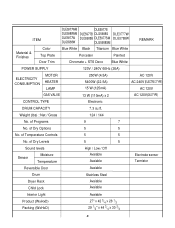
...7 No. of Temperature Controls 5 5 No. Weight (lbs) : Net / Gross 124 / 144 No. ITEM DLE5977WM DLE5977S DLE5988WM DLE5977B DLG5988S DLE3777W DLE5977W DLG5988B DLE5977SM DLG3788W DLG5988W DLG5988SM REMARK Material & Finishes Color Top Plate Door Trim Blue White Black Titanium Blue White Porcelain Painted Chromate + STS ...Deco Blue White POWER SUPPLY 120V / 240V 60Hz (26A) ELECTRICITY CONSUMPTION MOTOR HEATER LAMP 250W (4.5A) 5400W (22.5A) 15 W (125mA) AC 120V AC 240V (ELECTRIC TYPE) AC 120V GAS ...
...7 No. of Temperature Controls 5 5 No. Weight (lbs) : Net / Gross 124 / 144 No. ITEM DLE5977WM DLE5977S DLE5988WM DLE5977B DLG5988S DLE3777W DLE5977W DLG5988B DLE5977SM DLG3788W DLG5988W DLG5988SM REMARK Material & Finishes Color Top Plate Door Trim Blue White Black Titanium Blue White Porcelain Painted Chromate + STS ...Deco Blue White POWER SUPPLY 120V / 240V 60Hz (26A) ELECTRICITY CONSUMPTION MOTOR HEATER LAMP 250W (4.5A) 5400W (22.5A) 15 W (125mA) AC 120V AC 240V (ELECTRIC TYPE) AC 120V GAS ...
Service Manual
Page 13
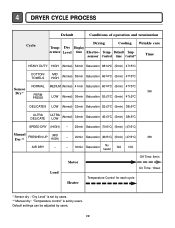
...±5°C) Manual FRESHEN UP Dry ** (MID HIGH) - 20min Saturation (66±5°C) (5min) (47±5°C) 3Hr AIR DRY - - 30min Saturation No heater N/A N/A Load Motor Heater Off Time: 6min On Time: 10sec Temperature Control for each cycle * Sensor dry : "Dry Level" is set by users. ** Manual dry : "Temperature control" is...
...±5°C) Manual FRESHEN UP Dry ** (MID HIGH) - 20min Saturation (66±5°C) (5min) (47±5°C) 3Hr AIR DRY - - 30min Saturation No heater N/A N/A Load Motor Heater Off Time: 6min On Time: 10sec Temperature Control for each cycle * Sensor dry : "Dry Level" is set by users. ** Manual dry : "Temperature control" is...

Service Manual
Page 15
... of terminal to terminal Open at 370°F ((Maximum) Close at 320°F Resistance value ∞ Resistance value < 1Ω • Gas type 15 Thermistor 9. Heater 8. Motor Test Procedure Measure resistance of terminal to terminal Resistance value : 100~800Ω • Gas type 12. Component 7. Frame Detect Measure resistance of terminal to...
... of terminal to terminal Open at 370°F ((Maximum) Close at 320°F Resistance value ∞ Resistance value < 1Ω • Gas type 15 Thermistor 9. Heater 8. Motor Test Procedure Measure resistance of terminal to terminal Resistance value : 100~800Ω • Gas type 12. Component 7. Frame Detect Measure resistance of terminal to...

Service Manual
Page 17
6 MOTOR DIAGRAM AND SCHEMATIC NOTE When checking Component, be sure to turn Power off, then do voltage discharge sufficiently. Contact On / Off by Centrifugal Switch STOP MODE (When Motor does not operate) RUN MODE (Motor operates) Centrifugal switch Centrifugal switch (Pull Drive forward) 17
6 MOTOR DIAGRAM AND SCHEMATIC NOTE When checking Component, be sure to turn Power off, then do voltage discharge sufficiently. Contact On / Off by Centrifugal Switch STOP MODE (When Motor does not operate) RUN MODE (Motor operates) Centrifugal switch Centrifugal switch (Pull Drive forward) 17

Service Manual
Page 19
...NC BL4 LAMP YELLOW 1 2 3 BELT SWITCH BLOWER THERMOSTAT GRAY BLUE BLUE BLUE 23 IGNITER RED 1212 BLUE 21 21 123 DOOR SWITCH MOTOR 2379 OVERLOAD PROTECTOR HI-LIMIT THERMOSTAT WHITE DC VALVE1 DC VALVE2 MOISTURE THERMISTOR FLAME SENSOR DETECTOR CENTRIFUGAL SWITCH RED WHITE NC NO GRAY SAFETY ... GRAY BL4 LAMP YELLOW 1 2 3 BELT SWITCH YELLOW BLUE BLUE HEATER 21 21 BLUE ORANGE RED NC 123 DOOR SWITCH WHITE 1 2 3 7 10 MOTOR OVERLOAD PROTECTOR MOISTURE THERMISTOR SENSOR RED SAFETY THERMOSTAT OUTER COIL INNER COIL CENTRIFUGAL SWITCH BLOWER WHITE THERMOSTAT RED RED HI -
...NC BL4 LAMP YELLOW 1 2 3 BELT SWITCH BLOWER THERMOSTAT GRAY BLUE BLUE BLUE 23 IGNITER RED 1212 BLUE 21 21 123 DOOR SWITCH MOTOR 2379 OVERLOAD PROTECTOR HI-LIMIT THERMOSTAT WHITE DC VALVE1 DC VALVE2 MOISTURE THERMISTOR FLAME SENSOR DETECTOR CENTRIFUGAL SWITCH RED WHITE NC NO GRAY SAFETY ... GRAY BL4 LAMP YELLOW 1 2 3 BELT SWITCH YELLOW BLUE BLUE HEATER 21 21 BLUE ORANGE RED NC 123 DOOR SWITCH WHITE 1 2 3 7 10 MOTOR OVERLOAD PROTECTOR MOISTURE THERMISTOR SENSOR RED SAFETY THERMOSTAT OUTER COIL INNER COIL CENTRIFUGAL SWITCH BLOWER WHITE THERMOSTAT RED RED HI -
Service Manual
Page 20
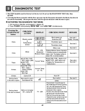
... ELECTRIC TYPE : Heater runs GAS TYPE : GAS Valve runs (Display the Temperature of Inside drum.) Gas valve See test 7 4 times Control Off During check, Motor & Heater Off + Lamp On + If the door is closed. Unit must be used for Factory test /Service test. Off + Lamp Off 70 ~ 239...Auto Off Door switch Lamp • Press Start button 1 time and then open Thermistor close See test 1 Display : See page See test 2 Once Motor Motor runs 70 ~ 239 Measured Moisture Value. Proceed again from the step 1 all the electric devices shut off in , display off) 2. Proceed again with...
... ELECTRIC TYPE : Heater runs GAS TYPE : GAS Valve runs (Display the Temperature of Inside drum.) Gas valve See test 7 4 times Control Off During check, Motor & Heater Off + Lamp On + If the door is closed. Unit must be used for Factory test /Service test. Off + Lamp Off 70 ~ 239...Auto Off Door switch Lamp • Press Start button 1 time and then open Thermistor close See test 1 Display : See page See test 2 Once Motor Motor runs 70 ~ 239 Measured Moisture Value. Proceed again from the step 1 all the electric devices shut off in , display off) 2. Proceed again with...
Service Manual
Page 23
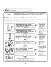
...(When discharging, contact the metal plug of Outlet Thermostat attached to turn Power off from • Motor Pulley. • Replace Idler Switch. • Check Motor.(Refer to Motor Bracket operate Level by drum belt? No fan will work. Measurement Condition Turn the Dryer's Power ...terminals? YES (Not operating Lever is closed . Is resistance below 1Ω between Connector "BL2- YES Measure while door is contacted. 23 Test 3 Motor test Caution Before measuring resistance, be sure to blower housing? " (Brown wire)? " (White wire) and "BL2- " (Yellow wire) and...
...(When discharging, contact the metal plug of Outlet Thermostat attached to turn Power off from • Motor Pulley. • Replace Idler Switch. • Check Motor.(Refer to Motor Bracket operate Level by drum belt? No fan will work. Measurement Condition Turn the Dryer's Power ...terminals? YES (Not operating Lever is closed . Is resistance below 1Ω between Connector "BL2- YES Measure while door is contacted. 23 Test 3 Motor test Caution Before measuring resistance, be sure to blower housing? " (Brown wire)? " (White wire) and "BL2- " (Yellow wire) and...

Service Manual
Page 25
...~60Ω between "WH3- YES • Door switch Check (Refer to Component testing.) • Check Lamp. (When opening Door, Drum motor and Trouble Symptom Heater run continuously; NO • Door switch Check (Refer to Component testing.) Measure while Door is closed . Display will not...off, and do voltage discharge. (When discharging, contact the metal plug of Power cord with earth line.) Door Opening is not sensed. (Drum motor will flash at 0.5 second intervals.) Measurement Condition After turning Dryer Power Off, measure resistance. " (Yellow wire) and "WH3- "(Black wire) ...
...~60Ω between "WH3- YES • Door switch Check (Refer to Component testing.) • Check Lamp. (When opening Door, Drum motor and Trouble Symptom Heater run continuously; NO • Door switch Check (Refer to Component testing.) Measure while Door is closed . Display will not...off, and do voltage discharge. (When discharging, contact the metal plug of Power cord with earth line.) Door Opening is not sensed. (Drum motor will flash at 0.5 second intervals.) Measurement Condition After turning Dryer Power Off, measure resistance. " (Yellow wire) and "WH3- "(Black wire) ...
Service Manual
Page 26
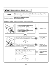
Check Motor. Check if the value of Power cord with earth line.) Trouble Symptom While operating, Heating will not work. Test 6 Heater switch test - Electric Type Caution ... , and do voltage discharge. (When discharging, contact the metal plug of measured resistance is below 1Ω between terminal NO and at RUN condition. • Check Motor and replace it. Is resistance between Heater terminal and below 1Ω between terminal TH2 (Safety Thermostat). YES Check Controller. TH3 TH2 1. YES Check if the...
Check Motor. Check if the value of Power cord with earth line.) Trouble Symptom While operating, Heating will not work. Test 6 Heater switch test - Electric Type Caution ... , and do voltage discharge. (When discharging, contact the metal plug of measured resistance is below 1Ω between terminal NO and at RUN condition. • Check Motor and replace it. Is resistance between Heater terminal and below 1Ω between terminal TH2 (Safety Thermostat). YES Check Controller. TH3 TH2 1. YES Check if the...

Service Manual
Page 33
Loosen belt from motor and idler pulleys. 4. Remove a screw by holding the drum lamp shield in place. 3. Replace the lamp shield and screw. 33 Disassemble the top plate. 2. Disassemble ...
Loosen belt from motor and idler pulleys. 4. Remove a screw by holding the drum lamp shield in place. 3. Replace the lamp shield and screw. 33 Disassemble the top plate. 2. Disassemble ...

Service Manual
Page 35
Remove Cover Gride. 4. Remove the Drum assembly. 4. Remove the fan. 7. Remove the Drum assembly. 4. Remove 3 screws. 3. Disconnect electrode sensor. 1. Remove 2 screws and cover(Air guide). 5. Remove the filter. 2. Remove the Cabinet Cover and Tub Drum [Front]. 3. Remove the bolt and washer. 6. Remove the Cabinet Cover and Tub Drum [Front]. 3. Remove 7 screws. 5. Disassemble the top plate. 2. Remove the Tub Drum [Rear] towards the front. 35 Disconnect the motor clamp and motor. 1. Disassembly the top plate. 2. 1.
Remove Cover Gride. 4. Remove the Drum assembly. 4. Remove the fan. 7. Remove the Drum assembly. 4. Remove 3 screws. 3. Disconnect electrode sensor. 1. Remove 2 screws and cover(Air guide). 5. Remove the filter. 2. Remove the Cabinet Cover and Tub Drum [Front]. 3. Remove the bolt and washer. 6. Remove the Cabinet Cover and Tub Drum [Front]. 3. Remove 7 screws. 5. Disassemble the top plate. 2. Remove the Tub Drum [Rear] towards the front. 35 Disconnect the motor clamp and motor. 1. Disassembly the top plate. 2. 1.

Service Manual
Page 39
12-3-1. Drum & Motor Assembly : Electric Type K120 F200 K400 K100 K140 K130 K222 K221 K210 K350 K240 F130 F110 F120 K230 K250 K251 K330 K320 K340 K250 K251 K360 K550 K560 K310 K620 K610 F140 K540 K510 K520 K640 K530 K651 K600 K650 39
12-3-1. Drum & Motor Assembly : Electric Type K120 F200 K400 K100 K140 K130 K222 K221 K210 K350 K240 F130 F110 F120 K230 K250 K251 K330 K320 K340 K250 K251 K360 K550 K560 K310 K620 K610 F140 K540 K510 K520 K640 K530 K651 K600 K650 39

