

Service Manual
Page 14
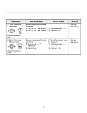
...value ∞ Resistance value < 5Ω Measure resistance of terminal to Open condition. Lever push (close) Resistance value ∞ 14 Outlet Thermostat ( Auto reset) • Check Top Marking : N85 4. Lamp holder Test Procedure Check result Remark Measure resistance of terminal Resistance value : ...Resistance value ∞ Resistance value < 1Ω The state that Knob is pressed is open Resistance value < 1Ω 2. Hi limit Thermostat (Auto reset) 3. to turn the power off • Check Top Marking : N130 2. CAUTION When checking the Component, be sure to...
...value ∞ Resistance value < 5Ω Measure resistance of terminal to Open condition. Lever push (close) Resistance value ∞ 14 Outlet Thermostat ( Auto reset) • Check Top Marking : N85 4. Lamp holder Test Procedure Check result Remark Measure resistance of terminal Resistance value : ...Resistance value ∞ Resistance value < 1Ω The state that Knob is pressed is open Resistance value < 1Ω 2. Hi limit Thermostat (Auto reset) 3. to turn the power off • Check Top Marking : N130 2. CAUTION When checking the Component, be sure to...
Service Manual
Page 16
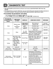
... reset) • Check Top Marking : N95 13. Outlet Thermostat (Manual reset) • Check Top Marking : N100 Test Procedure Measure resistance of terminal to terminal Open at 203 ± 7°F (95 ± 5°C) Close at ...
... reset) • Check Top Marking : N95 13. Outlet Thermostat (Manual reset) • Check Top Marking : N100 Test Procedure Measure resistance of terminal to terminal Open at 203 ± 7°F (95 ± 5°C) Close at ...

Service Manual
Page 19
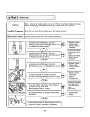
... RED NC 123 DOOR SWITCH WHITE 1 2 3 7 10 MOTOR OVERLOAD PROTECTOR MOISTURE THERMISTOR SENSOR RED SAFETY THERMOSTAT OUTER COIL INNER COIL CENTRIFUGAL SWITCH BLOWER WHITE THERMOSTAT RED RED HI - LIMIT THERMOSTAT ELECTRIC DRYER WIRING DIAGRAM RLM GAS DRYER WIRING DIAGRAM POWER CORD L1 BLACK RD3 3 2 N WHITE 1... WH3 3 1 2 BL2 34 1 2 YL2 2 1 WH3 321 BL3 321 1 3 56 8 7 6 5 4 3 2 COM 1 NO 1 2 GRAY NC BL4 LAMP YELLOW 1 2 3 BELT SWITCH BLOWER THERMOSTAT GRAY BLUE BLUE BLUE 23 IGNITER RED 1212 BLUE 21 21 123 DOOR SWITCH MOTOR 2379 OVERLOAD PROTECTOR HI-LIMIT...
... RED NC 123 DOOR SWITCH WHITE 1 2 3 7 10 MOTOR OVERLOAD PROTECTOR MOISTURE THERMISTOR SENSOR RED SAFETY THERMOSTAT OUTER COIL INNER COIL CENTRIFUGAL SWITCH BLOWER WHITE THERMOSTAT RED RED HI - LIMIT THERMOSTAT ELECTRIC DRYER WIRING DIAGRAM RLM GAS DRYER WIRING DIAGRAM POWER CORD L1 BLACK RD3 3 2 N WHITE 1... WH3 3 1 2 BL2 34 1 2 YL2 2 1 WH3 321 BL3 321 1 3 56 8 7 6 5 4 3 2 COM 1 NO 1 2 GRAY NC BL4 LAMP YELLOW 1 2 3 BELT SWITCH BLOWER THERMOSTAT GRAY BLUE BLUE BLUE 23 IGNITER RED 1212 BLUE 21 21 123 DOOR SWITCH MOTOR 2379 OVERLOAD PROTECTOR HI-LIMIT...
Service Manual
Page 20
.... Displays Moisture Sensor Operation: If moisture sensor is below 180, in normal condition. The display number is contacted with the Door open may trip the Thermostat attached to the Heater, therefore do not activate it manually. (Do not press the door switch to the step 4. • Press Start 3 times and then...
.... Displays Moisture Sensor Operation: If moisture sensor is below 180, in normal condition. The display number is contacted with the Door open may trip the Thermostat attached to the Heater, therefore do not activate it manually. (Do not press the door switch to the step 4. • Press Start 3 times and then...
Service Manual
Page 23
...White wire) and "BL2- " (Yellow wire)? NO YES • Replace Control. (Relay check) • Check Controller connector. • Replace Outlet • Thermostat. (Refer to 'Component') • Check Idler Assembly. • Drum Belt cuts off • Drum Belt takes off , and do voltage discharge. (When ...discharging, contact the metal plug of Outlet Thermostat attached to blower housing? Test 3 Motor test Caution Before measuring resistance, be sure to turn Power off from • Motor Pulley....
...White wire) and "BL2- " (Yellow wire)? NO YES • Replace Control. (Relay check) • Check Controller connector. • Replace Outlet • Thermostat. (Refer to 'Component') • Check Idler Assembly. • Drum Belt cuts off • Drum Belt takes off , and do voltage discharge. (When ...discharging, contact the metal plug of Outlet Thermostat attached to blower housing? Test 3 Motor test Caution Before measuring resistance, be sure to turn Power off from • Motor Pulley....
Service Manual
Page 26
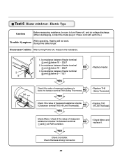
.... Is resistance between Heater terminal and below 1Ω between terminal TH2 (Safety Thermostat). NO YES • Replace TH2 (Safety Thermostat). NO • Replace Heater. NO YES • Replace TH3 (HI-Limit Thermostat). Check Harness-linking Connector. 26 TH3 TH2 1. Is resistance between Heater terminal and... below 1Ω between terminal TH3 (HI-Limit Thermostat). Check if the value of measured resistance is below 9 ~ 11Ω? YES Check Controller. Electric Type Caution ...
.... Is resistance between Heater terminal and below 1Ω between terminal TH2 (Safety Thermostat). NO YES • Replace TH2 (Safety Thermostat). NO • Replace Heater. NO YES • Replace TH3 (HI-Limit Thermostat). Check Harness-linking Connector. 26 TH3 TH2 1. Is resistance between Heater terminal and... below 1Ω between terminal TH3 (HI-Limit Thermostat). Check if the value of measured resistance is below 9 ~ 11Ω? YES Check Controller. Electric Type Caution ...
Service Manual
Page 27
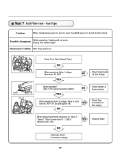
... is more than AC 90V? Trouble Symptom While operating, Heating will not work. Drying time takes longer. Test 7 GAS Valve test - YES NO • Check thermostat Hi limit Safety Igniter operates? (after Off ) YES • Change Valve NO • Harness check • Controller change 27 Gas Type Caution When measuring power...
... is more than AC 90V? Trouble Symptom While operating, Heating will not work. Drying time takes longer. Test 7 GAS Valve test - YES NO • Check thermostat Hi limit Safety Igniter operates? (after Off ) YES • Change Valve NO • Harness check • Controller change 27 Gas Type Caution When measuring power...


