Owners Manual
Page 20
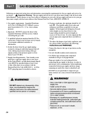
... MUST be provided at test pressure equal to do so can result in death, explosion, or fire. 20 WARNING! DO NOT attempt any disassembly of the dryer, any local codes or ordinances in accordance with the National Fuel Gas Code ANSI Z223.1. Gas supply requirements: Liquefied Petroleum ...should be installed as shown. ! Part 7 GAS REQUIREMENTS AND INSTRUCTIONS Following are less than 2/1 psi (3.45 kPa). 5. In the absence of any disassembly requires the attention and tools of 20 feet (6.1m). Important: DO NOT connect the dryer to inspect for a gas dryer must perform the LP Gas...
... MUST be provided at test pressure equal to do so can result in death, explosion, or fire. 20 WARNING! DO NOT attempt any disassembly of the dryer, any local codes or ordinances in accordance with the National Fuel Gas Code ANSI Z223.1. Gas supply requirements: Liquefied Petroleum ...should be installed as shown. ! Part 7 GAS REQUIREMENTS AND INSTRUCTIONS Following are less than 2/1 psi (3.45 kPa). 5. In the absence of any disassembly requires the attention and tools of 20 feet (6.1m). Important: DO NOT connect the dryer to inspect for a gas dryer must perform the LP Gas...

Service Manual
Page 3
... DIAGRAM AND SCHEMATIC 17 7. DIAGNOSTIC TEST ...20 9-1. TEST 1 120VAC ELECTRICAL SUPPLY 21 9-2. TEST 2 THERMISTOR TEST --- CONTROL PANEL & PLATE ASSEMBLY 37 12-2. CONTENTS 1. FEATURES AND BENEFITS ...6 3. DISASSEMBLY INSTRUCTIONS 30 12. SPECIFICATIONS ...4 2. OUT ...18 8. GAS TYPE 27 10. ELECTRIC TYPE 26 9-7. CHANGE GAS SETTING (NATURAL GAS, PROPANE GAS 28 11. CABINET & DOOR ASSEMBLY...
... DIAGRAM AND SCHEMATIC 17 7. DIAGNOSTIC TEST ...20 9-1. TEST 1 120VAC ELECTRICAL SUPPLY 21 9-2. TEST 2 THERMISTOR TEST --- CONTROL PANEL & PLATE ASSEMBLY 37 12-2. CONTENTS 1. FEATURES AND BENEFITS ...6 3. DISASSEMBLY INSTRUCTIONS 30 12. SPECIFICATIONS ...4 2. OUT ...18 8. GAS TYPE 27 10. ELECTRIC TYPE 26 9-7. CHANGE GAS SETTING (NATURAL GAS, PROPANE GAS 28 11. CABINET & DOOR ASSEMBLY...
Service Manual
Page 28
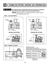
Initially, Natural Gas mode is on sale as a Service Part to authorized servicers only. Disassemble the pipe assembly. STEP 1 : VALVE SETTING Full open "Change screw" STEP 2 : ORIFICE CHANGE Orifice Close "Change screw" Remove 2 screws. Replace Natural Gas orifice with Propane ...
Initially, Natural Gas mode is on sale as a Service Part to authorized servicers only. Disassemble the pipe assembly. STEP 1 : VALVE SETTING Full open "Change screw" STEP 2 : ORIFICE CHANGE Orifice Close "Change screw" Remove 2 screws. Replace Natural Gas orifice with Propane ...

Service Manual
Page 30
Push the top plate back ward. 3. Lift the top plate 30 Remove 3 screws on the upper plate. 2. 11 DISASSEMBLY INSTRUCTIONS Disassemble and repair the unit only after pulling out power plug from the outlet. 1.
Push the top plate back ward. 3. Lift the top plate 30 Remove 3 screws on the upper plate. 2. 11 DISASSEMBLY INSTRUCTIONS Disassemble and repair the unit only after pulling out power plug from the outlet. 1.

Service Manual
Page 31
Pull the control panel assembly upward and then forward. 4. Remove 4 screws on the control panel frame. 2. Disassemble the control panel assembly. 31 Remove 2 screws on the PWB(PCB) assembly, main. 6. Disconnect the connectors. 3. Remove 9 screws on the PWB(PCB) assembly, display. 5. 1.
Pull the control panel assembly upward and then forward. 4. Remove 4 screws on the control panel frame. 2. Disassemble the control panel assembly. 31 Remove 2 screws on the PWB(PCB) assembly, main. 6. Disconnect the connectors. 3. Remove 9 screws on the PWB(PCB) assembly, display. 5. 1.

Service Manual
Page 32
Disassemble the top plate. 2. Remove 4 screws from the top of door switch. 32 Disconnect the harness of cabinet cover. 6. Remove 2 screws. 5. Disassemble the door assembly. 4. 1. Disassemble the control panel assembly. 3.
Disassemble the top plate. 2. Remove 4 screws from the top of door switch. 32 Disconnect the harness of cabinet cover. 6. Remove 2 screws. 5. Disassemble the door assembly. 4. 1. Disassemble the control panel assembly. 3.

Service Manual
Page 33
... Cover Cabinet. 3. Loosen belt from motor and idler pulleys. 4. Slide the shield up and remove. 4. Remove 4 screws. 5. Carefully remove Drum out. 1. Disassemble the top plate. -1 2. Remove the bulb and replace with a 15 watt, 120 volt candelabra-base bulb. 5. Disconnect the door lamp and electrode sensor connector.... 4. Remove a screw by holding the drum lamp shield in place. 3. 1. Remove the Cabinet Cover and Tub drum [front]. -2 3. Disassemble the door. 2. Disassemble the Tub Drum [Front]. -1 1. Replace the lamp shield and screw. 33...
... Cover Cabinet. 3. Loosen belt from motor and idler pulleys. 4. Slide the shield up and remove. 4. Remove 4 screws. 5. Carefully remove Drum out. 1. Disassemble the top plate. -1 2. Remove the bulb and replace with a 15 watt, 120 volt candelabra-base bulb. 5. Disconnect the door lamp and electrode sensor connector.... 4. Remove a screw by holding the drum lamp shield in place. 3. 1. Remove the Cabinet Cover and Tub drum [front]. -2 3. Disassemble the door. 2. Disassemble the Tub Drum [Front]. -1 1. Replace the lamp shield and screw. 33...

Service Manual
Page 35
Disassembly the top plate. 2. Remove 2 screws and cover(Air guide). 5. Disconnect the motor clamp and motor. 1. Remove Cover Gride. 4. Remove the bolt and washer. 6. Remove the fan. 7. Disassemble the top plate. 2. Remove the Drum assembly. 4. Remove the Drum assembly. 4. Remove 7 screws. 5. Remove the filter. 2. Remove the Cabinet Cover and Tub Drum [Front]. 3. Remove the Tub Drum [Rear] towards the front. 35 Disconnect electrode sensor. 1. Remove the Cabinet Cover and Tub Drum [Front]. 3. 1. Remove 3 screws. 3.
Disassembly the top plate. 2. Remove 2 screws and cover(Air guide). 5. Disconnect the motor clamp and motor. 1. Remove Cover Gride. 4. Remove the bolt and washer. 6. Remove the fan. 7. Disassemble the top plate. 2. Remove the Drum assembly. 4. Remove the Drum assembly. 4. Remove 7 screws. 5. Remove the filter. 2. Remove the Cabinet Cover and Tub Drum [Front]. 3. Remove the Tub Drum [Rear] towards the front. 35 Disconnect electrode sensor. 1. Remove the Cabinet Cover and Tub Drum [Front]. 3. 1. Remove 3 screws. 3.

Service Manual
Page 36
Disassemble the top plate. 2. Disconnect Air duct from the Tub Drum [Front] and Tub Drum [Rear]. 36 Remove the Cover Cabinet. 3. Remove filter and 2 screws. 4. Remove the Drum assembly and Tub Drum [Rear]. 4. Remove the Cover Cabinet and Tub Drum [Front]. 3. Disassemble the top plate. 2. Remove the air duct. 1. 1. Remove the roller from the Tub Drum [Front]. 5.
Disassemble the top plate. 2. Disconnect Air duct from the Tub Drum [Front] and Tub Drum [Rear]. 36 Remove the Cover Cabinet. 3. Remove filter and 2 screws. 4. Remove the Drum assembly and Tub Drum [Rear]. 4. Remove the Cover Cabinet and Tub Drum [Front]. 3. Disassemble the top plate. 2. Remove the air duct. 1. 1. Remove the roller from the Tub Drum [Front]. 5.


