
Owners Manual
Page 10
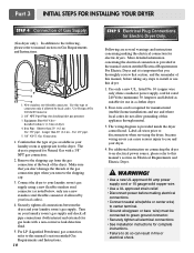
... servicing the dryer, because wiring errors can result in fire or electrical shock. Four-wire cord is provided inside the dryer control hood. The wiring diagram is required for Electric Dryer Only. Label all electrical connections • See installation instructions for Natural Gas with a non-corrosive leak detection fluid. 5. In addition...
... servicing the dryer, because wiring errors can result in fire or electrical shock. Four-wire cord is provided inside the dryer control hood. The wiring diagram is required for Electric Dryer Only. Label all electrical connections • See installation instructions for Natural Gas with a non-corrosive leak detection fluid. 5. In addition...
Owners Manual
Page 15
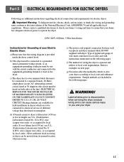
... 70 and all wires prior to disconnection when servicing the dryer, because wiring errors can be moved from its own terminal block that the wiring diagram is optional and subject to local code requirements. DO NOT CONNECT DRYER TO 110, 115, OR 120 VOLT CIRCUIT. d) If branch circuit to dryer is...
... 70 and all wires prior to disconnection when servicing the dryer, because wiring errors can be moved from its own terminal block that the wiring diagram is optional and subject to local code requirements. DO NOT CONNECT DRYER TO 110, 115, OR 120 VOLT CIRCUIT. d) If branch circuit to dryer is...
Owners Manual
Page 19
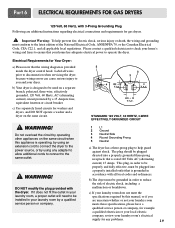
... laundry room by a 15 Ampere fuse, equivalent fusetron or circuit breaker. b) The dryer must be plugged into a properly grounded three-prong receptacle that the wiring diagram is designed to the same outlet. ! Electrical Requirements for Your Dryer: a) Please note that is rated 120 Volts AC (alternating current) 15 Amps. WARNING! c) Use...
... laundry room by a 15 Ampere fuse, equivalent fusetron or circuit breaker. b) The dryer must be plugged into a properly grounded three-prong receptacle that the wiring diagram is designed to the same outlet. ! Electrical Requirements for Your Dryer: a) Please note that is rated 120 Volts AC (alternating current) 15 Amps. WARNING! c) Use...
Owners Manual
Page 22
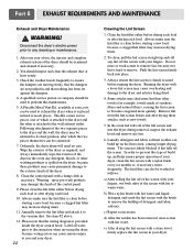
... a clogged lint filter may cause permanent damage to ensure the dampers are moving freely, that the dampers are not pushed in and that the wiring diagram is placed in the event any lint. 6. Always ensure the lint screen is likely blocked if lint falls off of the screen with your dryer...
... a clogged lint filter may cause permanent damage to ensure the dampers are moving freely, that the dampers are not pushed in and that the wiring diagram is placed in the event any lint. 6. Always ensure the lint screen is likely blocked if lint falls off of the screen with your dryer...

Service Manual
Page 3
... SCHEMATIC 17 7. WIRING DIAGRAM ...19 9. DIAGNOSTIC TEST ...20 9-1. TEST 6 HEATER SWITCH TEST - TEST 7 GAS VALVE TEST - GAS TYPE 27 10. CONTENTS 1. TEST 2 THERMISTOR TEST --- TEST 5 DOOR SWITCH TEST 25 9-6. ...
... SCHEMATIC 17 7. WIRING DIAGRAM ...19 9. DIAGNOSTIC TEST ...20 9-1. TEST 6 HEATER SWITCH TEST - TEST 7 GAS VALVE TEST - GAS TYPE 27 10. CONTENTS 1. TEST 2 THERMISTOR TEST --- TEST 5 DOOR SWITCH TEST 25 9-6. ...

Service Manual
Page 17
6 MOTOR DIAGRAM AND SCHEMATIC NOTE When checking Component, be sure to turn Power off, then do voltage discharge sufficiently. Contact On / Off by Centrifugal Switch STOP MODE (When Motor does not operate) RUN MODE (Motor operates) Centrifugal switch Centrifugal switch (Pull Drive forward) 17
6 MOTOR DIAGRAM AND SCHEMATIC NOTE When checking Component, be sure to turn Power off, then do voltage discharge sufficiently. Contact On / Off by Centrifugal Switch STOP MODE (When Motor does not operate) RUN MODE (Motor operates) Centrifugal switch Centrifugal switch (Pull Drive forward) 17

Service Manual
Page 19
LIMIT THERMOSTAT ELECTRIC DRYER WIRING DIAGRAM RLM GAS DRYER WIRING DIAGRAM POWER CORD L1 BLACK RD3 3 2 N WHITE 1 ELECTRONIC CONTROL RED PINK PINK BLUE ORANGE RED BROWN YELLOW BROWN PLC MODEM WHITE BLACK 1 ... VALVE1 DC VALVE2 MOISTURE THERMISTOR FLAME SENSOR DETECTOR CENTRIFUGAL SWITCH RED WHITE NC NO GRAY SAFETY THERMOSTAT GAS DRYER WIRING DIAGRAM PLC MODEM RED WHITE BLACK 8 WIRING DIAGRAM 19 RLM ELECTRIC DRYER WIRING DIAGRAM RD3 L1 BLACK 3 2 1 N WHITE 1 2 L2 3 WH3 12 34 BL2 1 2 ELECTRONIC CONTROL RD3 3 2 1 1 2 3 WH3 1 3 56 BROWN BROWN 8 7 6 5 4 ...
LIMIT THERMOSTAT ELECTRIC DRYER WIRING DIAGRAM RLM GAS DRYER WIRING DIAGRAM POWER CORD L1 BLACK RD3 3 2 N WHITE 1 ELECTRONIC CONTROL RED PINK PINK BLUE ORANGE RED BROWN YELLOW BROWN PLC MODEM WHITE BLACK 1 ... VALVE1 DC VALVE2 MOISTURE THERMISTOR FLAME SENSOR DETECTOR CENTRIFUGAL SWITCH RED WHITE NC NO GRAY SAFETY THERMOSTAT GAS DRYER WIRING DIAGRAM PLC MODEM RED WHITE BLACK 8 WIRING DIAGRAM 19 RLM ELECTRIC DRYER WIRING DIAGRAM RD3 L1 BLACK 3 2 1 N WHITE 1 2 L2 3 WH3 12 34 BL2 1 2 ELECTRONIC CONTROL RD3 3 2 1 1 2 3 WH3 1 3 56 BROWN BROWN 8 7 6 5 4 ...
Service Manual
Page 23
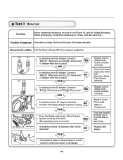
... test Caution Before measuring resistance, be sure to turn Power off from • Motor Pulley. • Replace Idler Switch. • Check Motor.(Refer to 'Motor Diagram & Check') • Check if Control Connector is contacted. 23
... test Caution Before measuring resistance, be sure to turn Power off from • Motor Pulley. • Replace Idler Switch. • Check Motor.(Refer to 'Motor Diagram & Check') • Check if Control Connector is contacted. 23

