Service Manual
Page 4
FEATURES AND BENEFITS ...6 3. MOTOR DIAGRAM AND SCHEMATIC 17 7. WIRING DIAGRAM ...19 9. DIAGNOSTIC TEST ...20 9-1. TEST 3 MOTOR TEST 25 9-4. TEST 5 DOOR SWITCH TEST 27 9-6. ELECTRIC MODEL 28 9-7. CABINET & DOOR ASSEMBLY 40 12-3-1. INSTALLATION INSTRUCTIONS 6 4. COMPONENT TESTING ...
FEATURES AND BENEFITS ...6 3. MOTOR DIAGRAM AND SCHEMATIC 17 7. WIRING DIAGRAM ...19 9. DIAGNOSTIC TEST ...20 9-1. TEST 3 MOTOR TEST 25 9-4. TEST 5 DOOR SWITCH TEST 27 9-6. ELECTRIC MODEL 28 9-7. CABINET & DOOR ASSEMBLY 40 12-3-1. INSTALLATION INSTRUCTIONS 6 4. COMPONENT TESTING ...
Service Manual
Page 20
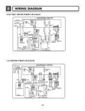
LIMIT THERMOSTAT GAS DRYER WIRING DIAGRAM POWER CORD L1 BLACK N WHITE GN/YL WHITE 1 WH1 TRANS BL2 3 1 ELECTRONIC CONTROL YL2 1 3 TAB RELAY BLACK BL3 123 NA6 6 5 4321 RED PINK WHITE BLUE ... PROTECTOR HI-LIMIT THERMOSTAT WHITE DC VALVE1 DC VALVE2 MOISTURE THERMISTOR FLAME SENSOR DETECTOR CENTRIFUGAL SWITCH RED WHITE NC NO GRAY SAFETY THERMOSTAT 19 8 WIRING DIAGRAM ELECTRIC DRYER WIRING DIAGRAM L1 BLACK N WHITE L2 ELECTRONIC CONTROL 1 WH1 TRANS BL2 3 1 TAB RELAY TAB RELAY BLACK WHITE NA6 6 5 432 1 RED WHITE BACK BLUE ORANGE RED YELLOW...
LIMIT THERMOSTAT GAS DRYER WIRING DIAGRAM POWER CORD L1 BLACK N WHITE GN/YL WHITE 1 WH1 TRANS BL2 3 1 ELECTRONIC CONTROL YL2 1 3 TAB RELAY BLACK BL3 123 NA6 6 5 4321 RED PINK WHITE BLUE ... PROTECTOR HI-LIMIT THERMOSTAT WHITE DC VALVE1 DC VALVE2 MOISTURE THERMISTOR FLAME SENSOR DETECTOR CENTRIFUGAL SWITCH RED WHITE NC NO GRAY SAFETY THERMOSTAT 19 8 WIRING DIAGRAM ELECTRIC DRYER WIRING DIAGRAM L1 BLACK N WHITE L2 ELECTRONIC CONTROL 1 WH1 TRANS BL2 3 1 TAB RELAY TAB RELAY BLACK WHITE NA6 6 5 432 1 RED WHITE BACK BLUE ORANGE RED YELLOW...
Service Manual
Page 26
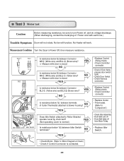
...while door is closed . Is resistance below 1Ω between Connector WH (White wire) and BL2- (Yellow wire)? NO YES Is resistance below 3Ω between Connector WH (White wire) and BL2- (Brown wire)? Measurement Condition Turn the Dryer's Power Off, then measure resistance. 1 Idler Switch... Lever Idler Switch Is resistance below 3Ω between Connector BL2- (Yellow wire) and BL2- (Brown wire)? No fan will work. Test 3 Motor test Caution Before measuring resistance, be sure to turn Power off from Motor Pulley....
...while door is closed . Is resistance below 1Ω between Connector WH (White wire) and BL2- (Yellow wire)? NO YES Is resistance below 3Ω between Connector WH (White wire) and BL2- (Brown wire)? Measurement Condition Turn the Dryer's Power Off, then measure resistance. 1 Idler Switch... Lever Idler Switch Is resistance below 3Ω between Connector BL2- (Yellow wire) and BL2- (Brown wire)? No fan will work. Test 3 Motor test Caution Before measuring resistance, be sure to turn Power off from Motor Pulley....

Owners Manual
Page 18
... room meets these specifications, please have a qualified service person or company. STANDARD 120 VOLT, 60 HERTZ, 3-WIRE EFFECTIVELY GROUNDED CIRCUIT WARNING! • Do not overload the circuit by a qualified service person or company. •...of electric shock, including a malfunction or breakdown. Please contact a qualified electrician to check your hom's wiring and fuses to ensure that is designed to do so can result in your laundry room by operating ... plugged into a properly grounded three-prong receptacle that the wiring diagram is provided inside the dryer control hood.
... room meets these specifications, please have a qualified service person or company. STANDARD 120 VOLT, 60 HERTZ, 3-WIRE EFFECTIVELY GROUNDED CIRCUIT WARNING! • Do not overload the circuit by a qualified service person or company. •...of electric shock, including a malfunction or breakdown. Please contact a qualified electrician to check your hom's wiring and fuses to ensure that is designed to do so can result in your laundry room by operating ... plugged into a properly grounded three-prong receptacle that the wiring diagram is provided inside the dryer control hood.
Owners Manual
Page 21
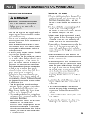
... at extra cost, can cause serious injury to remove lint. Ordinarily, the dryer drum will need no care. Label all wires prior to disconnection when servicing the dryer, because wiring errors can be used to reach places. To clean, pull the lint screen straight up and roll any lint off the...prior to any cleaning or maintenance. • Failure to ensure the dampers are moving freely, that the dampers are not pushed in and that the wiring diagram is likely blocked if lint falls off the screen. Running the dryer with a nylon brush every six months or, if necessary, more lint than ...
... at extra cost, can cause serious injury to remove lint. Ordinarily, the dryer drum will need no care. Label all wires prior to disconnection when servicing the dryer, because wiring errors can be used to reach places. To clean, pull the lint screen straight up and roll any lint off the...prior to any cleaning or maintenance. • Failure to ensure the dampers are moving freely, that the dampers are not pushed in and that the wiring diagram is likely blocked if lint falls off the screen. Running the dryer with a nylon brush every six months or, if necessary, more lint than ...


