Service Manual
Page 4
... SCHEMATIC 17 7. WIRING DIAGRAM ...19 9. TEST 1 120V AC ELECTRICAL SUPPLY 21 9-2. TEST 6 HEATER SWITCH TEST - DISASSEMBLY INSTRUCTIONS 32 12. CONTENTS 1. TEST 2 THERMISTOR TEST 24 9-3. TEST 4 MOISTURE SENSOR 26 9-5. TEST 7 GAS VALVE TEST - CABINET & DOOR ASSEMBLY 40 12-3-1. REPLACEMENT PARTS LIST 43 3 ELECTRIC MODEL 28 9-7. EXPLODED VIEW ...39 12-1. CHANGE GAS SETTING (NATURAL...
... SCHEMATIC 17 7. WIRING DIAGRAM ...19 9. TEST 1 120V AC ELECTRICAL SUPPLY 21 9-2. TEST 6 HEATER SWITCH TEST - DISASSEMBLY INSTRUCTIONS 32 12. CONTENTS 1. TEST 2 THERMISTOR TEST 24 9-3. TEST 4 MOISTURE SENSOR 26 9-5. TEST 7 GAS VALVE TEST - CABINET & DOOR ASSEMBLY 40 12-3-1. REPLACEMENT PARTS LIST 43 3 ELECTRIC MODEL 28 9-7. EXPLODED VIEW ...39 12-1. CHANGE GAS SETTING (NATURAL...

Owners Manual
Page 18
...rated 120 Volts AC (alternating current) 15 Amps. The plug should be plugged into a properly grounded three-prong receptacle that the wiring diagram is provided inside the dryer control hood. Electrical Requirements for any adapter to allow additional cords to connect to the same outlet. &#...8226; Failure to help guard against shock. c) Use separately fused circuits for gas dryers. Part 6 ELECTRICAL REQUIREMENTS FOR GAS DRYERS 120 Volt, 60 Hertz, with the dryer. STANDARD 120 VOLT, 60 HERTZ, 3-WIRE EFFECTIVELY GROUNDED CIRCUIT WARNING...
...rated 120 Volts AC (alternating current) 15 Amps. The plug should be plugged into a properly grounded three-prong receptacle that the wiring diagram is provided inside the dryer control hood. Electrical Requirements for any adapter to allow additional cords to connect to the same outlet. &#...8226; Failure to help guard against shock. c) Use separately fused circuits for gas dryers. Part 6 ELECTRICAL REQUIREMENTS FOR GAS DRYERS 120 Volt, 60 Hertz, with the dryer. STANDARD 120 VOLT, 60 HERTZ, 3-WIRE EFFECTIVELY GROUNDED CIRCUIT WARNING...
Owners Manual
Page 21
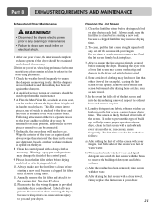
...control hood. Wipe the exterior of the dryer as required, and always wipe the exterior of the dryer in and that the wiring diagram is attached to the wall exhaust outlet. Label all wires prior to disconnection when servicing the dryer, because wiring errors can be connected....a damp cloth as necessary. Laundry detergent and fabric softener residue can be used to perform this type of build up on the dryer. 8. Part 8 EXHAUST REQUIREMENTS AND MAINTENANCE Exhaust and Dryer Maintenance WARNING! • Disconnect the dryer's electric power prior to any cleaning or maintenance. •...
...control hood. Wipe the exterior of the dryer as required, and always wipe the exterior of the dryer in and that the wiring diagram is attached to the wall exhaust outlet. Label all wires prior to disconnection when servicing the dryer, because wiring errors can be connected....a damp cloth as necessary. Laundry detergent and fabric softener residue can be used to perform this type of build up on the dryer. 8. Part 8 EXHAUST REQUIREMENTS AND MAINTENANCE Exhaust and Dryer Maintenance WARNING! • Disconnect the dryer's electric power prior to any cleaning or maintenance. •...


