

Service Manual
Page 2
... 3.2.5 MICRO SWITCH ASSEMBLY ...15 3.2.6 COIL ASSEMBLY, SOLENOID ...16 3.2.7 CONTROL PANEL ...16 3.2.8 FAN AND MOTOR...17 3.2.9 DRAIN PAN ...17 3.3 REFRIGERATING CYCLE ...18 3.3.1 CONDENSER, EVAPORATOR AND CAPILLARY TUBE 18 3.3.2 ROTARY COMPRESSOR ...18 3.4 HOW TO REPLACE REFRIGERATION SYSTEM 19 4. EXPLODED VIEWS ...23 6. PREFACE 1.1 SAFETY PRECAUTIONS ...3 1.2 FEATURES AND DIMENSIONS ...3 1.2.1 FEATURES...3 1.2.2 DIMENSIONS ...3 1.3 MODEL NAMES ...4 1.4 SPECIFICATIONS ...4 1.5 CONTROL TYPE...
... 3.2.5 MICRO SWITCH ASSEMBLY ...15 3.2.6 COIL ASSEMBLY, SOLENOID ...16 3.2.7 CONTROL PANEL ...16 3.2.8 FAN AND MOTOR...17 3.2.9 DRAIN PAN ...17 3.3 REFRIGERATING CYCLE ...18 3.3.1 CONDENSER, EVAPORATOR AND CAPILLARY TUBE 18 3.3.2 ROTARY COMPRESSOR ...18 3.4 HOW TO REPLACE REFRIGERATION SYSTEM 19 4. EXPLODED VIEWS ...23 6. PREFACE 1.1 SAFETY PRECAUTIONS ...3 1.2 FEATURES AND DIMENSIONS ...3 1.2.1 FEATURES...3 1.2.2 DIMENSIONS ...3 1.3 MODEL NAMES ...4 1.4 SPECIFICATIONS ...4 1.5 CONTROL TYPE...
Service Manual
Page 3
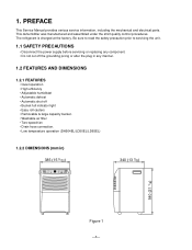
This dehumidifier was manufactured and assembled under the strict quality control procedures. The refrigerant is charged at the factory. PREFACE This Service Manual provides various service information, including the mechanical and electrical parts. 1. Be sure to read the safety ...
This dehumidifier was manufactured and assembled under the strict quality control procedures. The refrigerant is charged at the factory. PREFACE This Service Manual provides various service information, including the mechanical and electrical parts. 1. Be sure to read the safety ...
Service Manual
Page 4
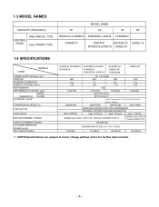
DH300EY6 DH404Y6 DH504ELY6 LD65ELY6 DH400EY6,LD40EY6 LD50ELY6 1.4 SPECIFICATIONS ITEMS MODELS POWER SUPPLY(Phase,V,Hz) INPUT(W) RUNNING CURRENT(A) ENERGY FACTOR(L/kw.h) REFRIGERANT REFRIGERANT CHARGE, oz(g) OPEN THERMISTOR CLOSE SOLENOID VALVE* COMPRESSOR MODEL No. 1.3 MODEL NAMES CAPACITY ... MOTOR ASSEMBLY,SINGLE SWITCH ASSEMBLY,MICRO OUTSIDED MENSIONS WxHxD,mm(in) NET WEIGHT,kg(lbs) DH305Y6, DH300MY6 DH300EY6 DH400MY6, LD40Y6 DH404EY6 DH400EY6, LD40EY6 DH504ELY6* LD50ELY6* DH500MY6 LD65ELY6* 480 4.8 1.23 3.70(105) 1Ø, 115V,60Hz 58 0 560 5.7 5.4 1.36 1.75 R22 4.41(...
DH300EY6 DH404Y6 DH504ELY6 LD65ELY6 DH400EY6,LD40EY6 LD50ELY6 1.4 SPECIFICATIONS ITEMS MODELS POWER SUPPLY(Phase,V,Hz) INPUT(W) RUNNING CURRENT(A) ENERGY FACTOR(L/kw.h) REFRIGERANT REFRIGERANT CHARGE, oz(g) OPEN THERMISTOR CLOSE SOLENOID VALVE* COMPRESSOR MODEL No. 1.3 MODEL NAMES CAPACITY ... MOTOR ASSEMBLY,SINGLE SWITCH ASSEMBLY,MICRO OUTSIDED MENSIONS WxHxD,mm(in) NET WEIGHT,kg(lbs) DH305Y6, DH300MY6 DH300EY6 DH400MY6, LD40Y6 DH404EY6 DH400EY6, LD40EY6 DH504ELY6* LD50ELY6* DH500MY6 LD65ELY6* 480 4.8 1.23 3.70(105) 1Ø, 115V,60Hz 58 0 560 5.7 5.4 1.36 1.75 R22 4.41(...

Service Manual
Page 6
... coil and drains into a bucket (or through the bucket into the front grille or out the rear grille. Dry, clean air is drawn over a cold refrigerated dehumidifying coil. s Close all sides of dehumidifier in its place, the unit again turns itself on. 1.6.4 AUTO DEFROST When frost builds up to be emptied...
... coil and drains into a bucket (or through the bucket into the front grille or out the rear grille. Dry, clean air is drawn over a cold refrigerated dehumidifying coil. s Close all sides of dehumidifier in its place, the unit again turns itself on. 1.6.4 AUTO DEFROST When frost builds up to be emptied...
Service Manual
Page 17
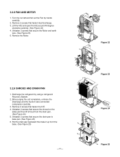
Turn the nut left and full out the Fan by using a refrigerant Recovery System. 2. Unfasten 2 screws that secure the shroud on the sides and then lift shroud from the base. (See Figure 25) -17- Lift the H/E and ... pan. (See Figure 24) 5. Figure 22 Figure 23 Figure 24 Figure 25 Remove 2 screws that fasten Heat Exchange. 3. Remove 2 screws that fasten the H/E. 4. Discharge the refrigerant by hands carefully. 2.
Turn the nut left and full out the Fan by using a refrigerant Recovery System. 2. Unfasten 2 screws that secure the shroud on the sides and then lift shroud from the base. (See Figure 25) -17- Lift the H/E and ... pan. (See Figure 24) 5. Figure 22 Figure 23 Figure 24 Figure 25 Remove 2 screws that fasten Heat Exchange. 3. Remove 2 screws that fasten the H/E. 4. Discharge the refrigerant by hands carefully. 2.
Service Manual
Page 18
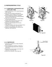
.... (See Figure 28) 8. Lift the H/E and open the H/E around 45 degree counterclockwise carefully. 5. Discharge the refrigerant by using a refrigerant recovery system. 3. Remove the compressor. (See Figure 29) Using Rotary Compressor models Figure 29 -18- Remove 4 screws...the H/E. (See Figure 26) 4. Pierce the pinch-off tube to discharge the refrigerant, using a refrigerant Recovery System. 2. Remove the H/E assembly from the orifice. (See Figure 27) 7. 3.3 REFRIGERATING CYCLE 3.3.1 CONDENSER, EVAPORATOR AND CAPILLARY TUBE 1. Remove the insulation on the Heater/Evaporator...
.... (See Figure 28) 8. Lift the H/E and open the H/E around 45 degree counterclockwise carefully. 5. Discharge the refrigerant by using a refrigerant recovery system. 3. Remove the compressor. (See Figure 29) Using Rotary Compressor models Figure 29 -18- Remove 4 screws...the H/E. (See Figure 26) 4. Pierce the pinch-off tube to discharge the refrigerant, using a refrigerant Recovery System. 2. Remove the H/E assembly from the orifice. (See Figure 27) 7. 3.3 REFRIGERATING CYCLE 3.3.1 CONDENSER, EVAPORATOR AND CAPILLARY TUBE 1. Remove the insulation on the Heater/Evaporator...
Service Manual
Page 19
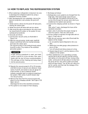
... you installed as the system was opened. 2) Connect the charging cylinder as shown in place on the charging cylinder. b. 3.4 HOW TO REPLACE THE REFRIGERATION SYSTEM 1. The vacuum pump is still closed . Recharge as illustrated in the suction line through valves A and B to drop. If the total charge... by means of vacuum are charged from the pinch-off tubes with the two full turns counterclockwise. Open valve C. Do not add the liquid refrigerant to 30 lbs. Turn off tube about 2 inches from the High-side. d. Using a tube cutter, cut the pinch-off valve B and ...
... you installed as the system was opened. 2) Connect the charging cylinder as shown in place on the charging cylinder. b. 3.4 HOW TO REPLACE THE REFRIGERATION SYSTEM 1. The vacuum pump is still closed . Recharge as illustrated in the suction line through valves A and B to drop. If the total charge... by means of vacuum are charged from the pinch-off tubes with the two full turns counterclockwise. Open valve C. Do not add the liquid refrigerant to 30 lbs. Turn off tube about 2 inches from the High-side. d. Using a tube cutter, cut the pinch-off valve B and ...

Service Manual
Page 22
..., if externally mounted. The bucket should be loose. Move dehumidifier for a restriction. Check electrical circuit. Leak in electrical circuit Unit pressures not equalized Capacitor Wiring Refrigeration system Stuck compressor Overload protector (OLP) REMEDY If cracked, out of Motor Assembly The bucket is high, remove the OLP, cool, and retest.) -22- Check...
..., if externally mounted. The bucket should be loose. Move dehumidifier for a restriction. Check electrical circuit. Leak in electrical circuit Unit pressures not equalized Capacitor Wiring Refrigeration system Stuck compressor Overload protector (OLP) REMEDY If cracked, out of Motor Assembly The bucket is high, remove the OLP, cool, and retest.) -22- Check...