
User Manual
Page 10
... have been removed, altered or cannot be provided by a KitchenAid designated service company. W10205937A SP PN W10205938 © 2008. KITCHENAID SHALL NOT BE LIABLE FOR INCIDENTAL OR CONSEQUENTIAL DAMAGES. Replacement parts or repair labor on the right-hand or left-hand side of the dishwasher interior. LIMITATION OF REMEDIES; Cosmetic damage, including scratches, dents...
... have been removed, altered or cannot be provided by a KitchenAid designated service company. W10205937A SP PN W10205938 © 2008. KITCHENAID SHALL NOT BE LIABLE FOR INCIDENTAL OR CONSEQUENTIAL DAMAGES. Replacement parts or repair labor on the right-hand or left-hand side of the dishwasher interior. LIMITATION OF REMEDIES; Cosmetic damage, including scratches, dents...
Installation Instructions
Page 2
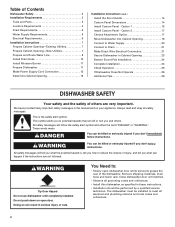
...important safety messages in Cabinet Opening 23 Bottom Sound Pad Installation 24 Complete Installation 24 Check Operation 26 If Dishwasher Does Not Operate 26 Additional Tips 26 DISHWASHER SAFETY Your safety and the safety of injury, and tell you...8226; Observe all governing codes and ordinances. • Install this manual and on open dishwasher door while someone grasps the rear of Contents Dishwasher Safety 2 Installation Requirements 3 Tools and Parts 3 Location Requirements 4 Drain Requirements 6 Water Supply Requirements 6 Electrical Requirements 6 Installation ...
...important safety messages in Cabinet Opening 23 Bottom Sound Pad Installation 24 Complete Installation 24 Check Operation 26 If Dishwasher Does Not Operate 26 Additional Tips 26 DISHWASHER SAFETY Your safety and the safety of injury, and tell you...8226; Observe all governing codes and ordinances. • Install this manual and on open dishwasher door while someone grasps the rear of Contents Dishwasher Safety 2 Installation Requirements 3 Tools and Parts 3 Location Requirements 4 Drain Requirements 6 Water Supply Requirements 6 Electrical Requirements 6 Installation ...

Installation Instructions
Page 3
...*Must be made by a licensed electrical installer. Parts needed : Copp O.D. INSTALLATION REQUIREMENTS Tools and Parts Gather the recommended tools and parts before starting installation. Read and follow the instructions provided with dishwasher Shallow pan Wood block Parts supplied: Drain hose clamps (2) (1 large and... front panels) †® TORX is recommended when installing a dishwasher under a wood countertop. In addition, for purchase in dishwasher Other useful items you may need: Flashlight Bath towel Other parts you may also need: (3.81-5.0 cm) Screw-type clamps (3...
...*Must be made by a licensed electrical installer. Parts needed : Copp O.D. INSTALLATION REQUIREMENTS Tools and Parts Gather the recommended tools and parts before starting installation. Read and follow the instructions provided with dishwasher Shallow pan Wood block Parts supplied: Drain hose clamps (2) (1 large and... front panels) †® TORX is recommended when installing a dishwasher under a wood countertop. In addition, for purchase in dishwasher Other useful items you may need: Flashlight Bath towel Other parts you may also need: (3.81-5.0 cm) Screw-type clamps (3...

Installation Instructions
Page 4
...locations require a 2" (5.1 cm) minimum clearance between motor and flooring. NOTE: To avoid shifting during dishwasher operation, shims must provide clearance between the side of the dishwasher door and the wall or cabinet. • square opening for proper operation and appearance. • cabinet... a period of your dealer for loading and unloading dishes. The location where the dishwasher will be left unused for installing underneath the countertops. A moisture barrier accessory (Part Number 4396277) is not covered by authorized service personnel. Motor should not touch the...
...locations require a 2" (5.1 cm) minimum clearance between motor and flooring. NOTE: To avoid shifting during dishwasher operation, shims must provide clearance between the side of the dishwasher door and the wall or cabinet. • square opening for proper operation and appearance. • cabinet... a period of your dealer for loading and unloading dishes. The location where the dishwasher will be left unused for installing underneath the countertops. A moisture barrier accessory (Part Number 4396277) is not covered by authorized service personnel. Motor should not touch the...
Installation Instructions
Page 6
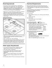
...8322;" minimum I.D. latest edition and all local codes and ordinances. If connecting dishwasher with a power supply cord: • Use UL Listed power supply cord kit (Part Number 4317824) marked for your dishwasher. If connecting dishwasher with direct wiring: • Use flexible, armored or nonmetallic sheathed, copper wire...to use a new drain hose with compression fitting or flexible braided water supply line (Part Number 4396897RP) NOTE: ¹⁄₂" minimum plastic tubing is resistant to the dishwasher opening. If drain hose is not long enough, use an air gap if the ...
...8322;" minimum I.D. latest edition and all local codes and ordinances. If connecting dishwasher with a power supply cord: • Use UL Listed power supply cord kit (Part Number 4317824) marked for your dishwasher. If connecting dishwasher with direct wiring: • Use flexible, armored or nonmetallic sheathed, copper wire...to use a new drain hose with compression fitting or flexible braided water supply line (Part Number 4396897RP) NOTE: ¹⁄₂" minimum plastic tubing is resistant to the dishwasher opening. If drain hose is not long enough, use an air gap if the ...

Installation Instructions
Page 8
... side of cabinet opening dimensions. 2 Direct Wire-Prepare hole (15.2 6" cm) Route cable from moving when dishwasher is in right-hand cabinet side or rear. Metal cabinet: Cover hole with grommet included with grommet (Part Number 302797 - Metal cabinet: Cover hole with power supply cord kit. 2 Power Supply Cord-Prepare hole 3 Direct...
... side of cabinet opening dimensions. 2 Direct Wire-Prepare hole (15.2 6" cm) Route cable from moving when dishwasher is in right-hand cabinet side or rear. Metal cabinet: Cover hole with grommet included with grommet (Part Number 302797 - Metal cabinet: Cover hole with power supply cord kit. 2 Power Supply Cord-Prepare hole 3 Direct...

Installation Instructions
Page 12
... panel. 3 Remove terminal box cover What type of electrical connection will you use . 4 Route cord so that it does not touch dishwasher motor to lower part of dishwasher door frame and place dishwasher on wire connectors (included with the power supply cord kit. 12 Do not use door panel as a worktable without first covering...
... panel. 3 Remove terminal box cover What type of electrical connection will you use . 4 Route cord so that it does not touch dishwasher motor to lower part of dishwasher door frame and place dishwasher on wire connectors (included with the power supply cord kit. 12 Do not use door panel as a worktable without first covering...

Installation Instructions
Page 18
... keeps the bracket in back or other injury. 1 Stand dishwasher upright Using two or more people, stand dishwasher upright. NOTE: Do not attach the dishwasher. NOTE: Do not attach the dishwasher. Option 2, Dishwasher side attachment: NOTE: Remove the brackets from the parts package. 1 Break end of the dishwasher. NOTE: Save the buttons to keep screws from falling...
... keeps the bracket in back or other injury. 1 Stand dishwasher upright Using two or more people, stand dishwasher upright. NOTE: Do not attach the dishwasher. NOTE: Do not attach the dishwasher. Option 2, Dishwasher side attachment: NOTE: Remove the brackets from the parts package. 1 Break end of the dishwasher. NOTE: Save the buttons to keep screws from falling...

Installation Instructions
Page 21
... Direct Wire Electrical Connection NOTE: If the power supply cord was connected earlier, proceed to "Secure Dishwasher in drain hose. Visit www.kitchenaid.com/watersupply under FAQ tab. Visit www.kitchenaid.com/drain under FAQ tab. Place the small green drain hose clamp onto the small end of this... 21 Push the new drain hose into terminal box Route cable so that it does not touch dishwasher motor or lower part of this step. If needed , see website for animated representation of dishwasher tub. 2 Check for leaks Place paper towel under drain hose to catch any water in Cabinet...
... Direct Wire Electrical Connection NOTE: If the power supply cord was connected earlier, proceed to "Secure Dishwasher in drain hose. Visit www.kitchenaid.com/watersupply under FAQ tab. Visit www.kitchenaid.com/drain under FAQ tab. Place the small green drain hose clamp onto the small end of this... 21 Push the new drain hose into terminal box Route cable so that it does not touch dishwasher motor or lower part of this step. If needed , see website for animated representation of dishwasher tub. 2 Check for leaks Place paper towel under drain hose to catch any water in Cabinet...

Installation Instructions
Page 25
Failure to the lower panel. Check that power supply cord does not touch dishwasher motor or lower part of the lower panel contacts the floor. Using a Phillips or ¹⁄₄" screwdriver, reinstall the screws through the holes in the access panel and ... can result in the lower panel. 3 Check lower panel edge WARNING Electrical Shock Hazard Plug into a grounded 3 prong outlet Check that the lower edge of dishwasher tub. Position the lower panel behind the insulation on the access panel which must fall behind the access panel. Check that grounding clip is insulation...
Failure to the lower panel. Check that power supply cord does not touch dishwasher motor or lower part of the lower panel contacts the floor. Using a Phillips or ¹⁄₄" screwdriver, reinstall the screws through the holes in the access panel and ... can result in the lower panel. 3 Check lower panel edge WARNING Electrical Shock Hazard Plug into a grounded 3 prong outlet Check that the lower edge of dishwasher tub. Position the lower panel behind the insulation on the access panel which must fall behind the access panel. Check that grounding clip is insulation...

Installation Instructions
Page 26
...the door within 3 seconds. Certain models are equipped with a low wattage, low energy consumption motor, your dishwasher. ❏ Check that all parts have all tools used. ❏ Start dishwasher and allow it again. (You must make sure the door is used with rinse aid for future reference....optical water sensor so the first cycle will run longer to calibrate to ensure exceptional cleaning. Additional Tips Expect longer wash times. Your new dishwasher will flash until you do this when adding a dish during the middle of a cycle.) NOTE: If a braided supply hose is ...
...the door within 3 seconds. Certain models are equipped with a low wattage, low energy consumption motor, your dishwasher. ❏ Check that all parts have all tools used. ❏ Start dishwasher and allow it again. (You must make sure the door is used with rinse aid for future reference....optical water sensor so the first cycle will run longer to calibrate to ensure exceptional cleaning. Additional Tips Expect longer wash times. Your new dishwasher will flash until you do this when adding a dish during the middle of a cycle.) NOTE: If a braided supply hose is ...
Parts Diagram
Page 1
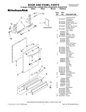
DESCRIPTION 1 Literature Parts W10056407 Instructions, Installation W10247455 Energy Guide W10205938 Guide, Use & Care Spanish W10205937 Guide, Use & Care English/French W10142800 Tech Sheet 2 Arm, Hinge 8534854... 16 Nameplate W10021860 Black W10021870 White W10021880 Biscuit W10021850 Stainless 17 2004333 Nut 18 W10123421 Screw 11−09 Litho In U.S.A. (MLR)(bay) 1 Part No. Part No. No. W10306068 Rev.A DOOR AND PANEL PARTS UNDERCOUNTER DISHWASHER For Models: KUDS40FVBL3, KUDS40FVWH3, KUDS40FVBT3, KUDS40FVSS3 (Black) (White) (Biscuit) (Stainless) Illus.
DESCRIPTION 1 Literature Parts W10056407 Instructions, Installation W10247455 Energy Guide W10205938 Guide, Use & Care Spanish W10205937 Guide, Use & Care English/French W10142800 Tech Sheet 2 Arm, Hinge 8534854... 16 Nameplate W10021860 Black W10021870 White W10021880 Biscuit W10021850 Stainless 17 2004333 Nut 18 W10123421 Screw 11−09 Litho In U.S.A. (MLR)(bay) 1 Part No. Part No. No. W10306068 Rev.A DOOR AND PANEL PARTS UNDERCOUNTER DISHWASHER For Models: KUDS40FVBL3, KUDS40FVWH3, KUDS40FVBT3, KUDS40FVSS3 (Black) (White) (Biscuit) (Stainless) Illus.

Parts Diagram
Page 2
CONTROL PANEL PARTS For Models: KUDS40FVBL3, KUDS40FVWH3, KUDS40FVBT3, KUDS40FVSS3 (Black) (White) (Biscuit) (Stainless) Illus. DESCRIPTION 1 Console Assembly W10249994 Black W10249995 White W10249996 Biscuit W10249997 Midnight Grey 2 W10077360 Latch Assembly 3 8546546 Clip, BI−Metal 4 W10208674 Control, Electronic 5 661663 BI−Metal 6 W10255029 Switch, Door 7 3369051 Screw 2 W10306068 No. Part No.
CONTROL PANEL PARTS For Models: KUDS40FVBL3, KUDS40FVWH3, KUDS40FVBT3, KUDS40FVSS3 (Black) (White) (Biscuit) (Stainless) Illus. DESCRIPTION 1 Console Assembly W10249994 Black W10249995 White W10249996 Biscuit W10249997 Midnight Grey 2 W10077360 Latch Assembly 3 8546546 Clip, BI−Metal 4 W10208674 Control, Electronic 5 661663 BI−Metal 6 W10255029 Switch, Door 7 3369051 Screw 2 W10306068 No. Part No.

Parts Diagram
Page 3
.... DESCRIPTION 11 W10224470 Wiring Harness 12 W10177098 Screw 13 8535660 Seal, Console/door 14 8535637 Bracket, Dispenser 15 8533965 Screw 16 8531865 Shield, Dispenser W10306068 3 Part No. DESCRIPTION 6 8269259 Gasket, Vent 7 W10077877 Deflector, Vent (Also Order Item 6) 8 W10224431 Dispenser, Assembly 9 W10077881 Knob, Rinse Aid 10 8545608 Harness, Vent Motor Illus. No...
.... DESCRIPTION 11 W10224470 Wiring Harness 12 W10177098 Screw 13 8535660 Seal, Console/door 14 8535637 Bracket, Dispenser 15 8533965 Screw 16 8531865 Shield, Dispenser W10306068 3 Part No. DESCRIPTION 6 8269259 Gasket, Vent 7 W10077877 Deflector, Vent (Also Order Item 6) 8 W10224431 Dispenser, Assembly 9 W10077881 Knob, Rinse Aid 10 8545608 Harness, Vent Motor Illus. No...

Parts Diagram
Page 4
Part No. DESCRIPTION 1 8268892 Lever, Overflow Switch 2 8531412 Hose, Inlet 3 W10195536 Water Inlet (Also Order Items 4 & 5) 4 8531323 Gasket 5 W10213826 Nut, Inlet (Also Order Item 4) 6 371505 Clamp, ..., Overfill Control 10 8545946 Standpipe, Overfill (Includes Item 11) 11 8531743 Gasket, Flat 12 9741998 Nut, Standpipe 13 W10077871 Float & Retainer Assembly 14 8269297 Miscellaneous Parts Bag (Includes 2 Screws & 2 Hose Clamps) 15 356138 Clamp, Hose 16 W10137608 Drain Loop with Check Valve 4 W10306068 No. FILL, DRAIN AND OVERFILL...
Part No. DESCRIPTION 1 8268892 Lever, Overflow Switch 2 8531412 Hose, Inlet 3 W10195536 Water Inlet (Also Order Items 4 & 5) 4 8531323 Gasket 5 W10213826 Nut, Inlet (Also Order Item 4) 6 371505 Clamp, ..., Overfill Control 10 8545946 Standpipe, Overfill (Includes Item 11) 11 8531743 Gasket, Flat 12 9741998 Nut, Standpipe 13 W10077871 Float & Retainer Assembly 14 8269297 Miscellaneous Parts Bag (Includes 2 Screws & 2 Hose Clamps) 15 356138 Clamp, Hose 16 W10137608 Drain Loop with Check Valve 4 W10306068 No. FILL, DRAIN AND OVERFILL...

Parts Diagram
Page 5
TUB AND FRAME PARTS For Models: KUDS40FVBL3, KUDS40FVWH3, KUDS40FVBT3, KUDS40FVSS3 (Black) (White) (Biscuit) (Stainless) W10306068 5
TUB AND FRAME PARTS For Models: KUDS40FVBL3, KUDS40FVWH3, KUDS40FVBT3, KUDS40FVSS3 (Black) (White) (Biscuit) (Stainless) W10306068 5

Parts Diagram
Page 6
... Actuator Assembly 19 3400892 Screw 20 8268991 Cover, Terminal Box 21 W10158291 Cable, Door Balance 22 304666 Retainer, Push 23 8573239 Shield, Sound Tub 24 9742648 Bracket, Thermostat 25 661566 Thermostat 26 W10077370 Strike, Latch 27 W10082769 Motor, Wax 28 3378128 Washer, Pronged Cup 29 3400014 Screw 30 W10078083 ...Wheel & Mount Assembly (Also Order Item 31) 31 9743002 Gasket, Bracket Mounting 6 W10306068 TUB AND FRAME PARTS For Models: KUDS40FVBL3, KUDS40FVWH3, KUDS40FVBT3, KUDS40FVSS3 (Black) (White) (Biscuit) (Stainless) Illus. No.
... Actuator Assembly 19 3400892 Screw 20 8268991 Cover, Terminal Box 21 W10158291 Cable, Door Balance 22 304666 Retainer, Push 23 8573239 Shield, Sound Tub 24 9742648 Bracket, Thermostat 25 661566 Thermostat 26 W10077370 Strike, Latch 27 W10082769 Motor, Wax 28 3378128 Washer, Pronged Cup 29 3400014 Screw 30 W10078083 ...Wheel & Mount Assembly (Also Order Item 31) 31 9743002 Gasket, Bracket Mounting 6 W10306068 TUB AND FRAME PARTS For Models: KUDS40FVBL3, KUDS40FVWH3, KUDS40FVBT3, KUDS40FVSS3 (Black) (White) (Biscuit) (Stainless) Illus. No.

Parts Diagram
Page 7
PUMP AND MOTOR PARTS For Models: KUDS40FVBL3, KUDS40FVWH3, KUDS40FVBT3, KUDS40FVSS3 (Black) (White) (Biscuit) (Stainless) W10306068 7
PUMP AND MOTOR PARTS For Models: KUDS40FVBL3, KUDS40FVWH3, KUDS40FVBT3, KUDS40FVSS3 (Black) (White) (Biscuit) (Stainless) W10306068 7

Parts Diagram
Page 8
... 8531017 Impeller Kit (Also Order Item 19) 21 8268403 Face Seal Assembly (Also Order Item 19) 22 356138 Clamp, Hose 23 W10134017 Optical Water Indicator 24 W10216724 Capacitor 8 W10306068 Part No. PUMP AND MOTOR PARTS For Models: KUDS40FVBL3, KUDS40FVWH3, KUDS40FVBT3, KUDS40FVSS3 (Black) (White) (Biscuit) (Stainless) Illus. No.
... 8531017 Impeller Kit (Also Order Item 19) 21 8268403 Face Seal Assembly (Also Order Item 19) 22 356138 Clamp, Hose 23 W10134017 Optical Water Indicator 24 W10216724 Capacitor 8 W10306068 Part No. PUMP AND MOTOR PARTS For Models: KUDS40FVBL3, KUDS40FVWH3, KUDS40FVBT3, KUDS40FVSS3 (Black) (White) (Biscuit) (Stainless) Illus. No.

Parts Diagram
Page 9
No. UPPER WASH AND RINSE PARTS For Models: KUDS40FVBL3, KUDS40FVWH3, KUDS40FVBT3, KUDS40FVSS3 (Black) (White) (Biscuit) (Stainless) W10306068 Illus. Part No. DESCRIPTION 1 W10077859 Feed Tube Assembly (Also Includes Item 3) 2 8533889 Screw 3 8557720 Sprayarm, 3rd Level 4 W10118464 Cover, Screw 5 W10082867 Mount 6 W10082949 Manifold 7 W10082832 Hanger 8 8268433 Seal, Sprayarm 9 W10082831 Probe, Manifold 10 W10082841 Sprayarm 11 W10077600 Manifold, Spray Zone 12 W10077903 Valve Assembly, Manifold 9
No. UPPER WASH AND RINSE PARTS For Models: KUDS40FVBL3, KUDS40FVWH3, KUDS40FVBT3, KUDS40FVSS3 (Black) (White) (Biscuit) (Stainless) W10306068 Illus. Part No. DESCRIPTION 1 W10077859 Feed Tube Assembly (Also Includes Item 3) 2 8533889 Screw 3 8557720 Sprayarm, 3rd Level 4 W10118464 Cover, Screw 5 W10082867 Mount 6 W10082949 Manifold 7 W10082832 Hanger 8 8268433 Seal, Sprayarm 9 W10082831 Probe, Manifold 10 W10082841 Sprayarm 11 W10077600 Manifold, Spray Zone 12 W10077903 Valve Assembly, Manifold 9


