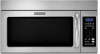
Dimension Guide
Page 1
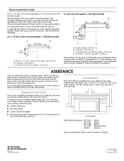
...90° elbows = 20 ft (6.1 m) B. 1 wall cap = 40 ft (12.2 m) C. 1 rectangular to change materials and specifications without notice. Instructions packed with a fuse or circuit breaker. or 20-amp fused electrical supply with product. One 3 " x 10" (8.3 x 25.4 cm) 90° ...(7.6 m) B. 1 wall cap = 40 ft (12.2 m) C. 2 ft (0.6 m) + 6 ft (1.8 m) straight = 8 ft (2.4 m) A. 2" x 4" wall stud B. For complete details, see Installation our products, we reserve the right to improve Dimensions are for either type of range/cooktop below. Ref. Roof cap: 3 " x 10" = 24 ft (8.3 x 25.4 cm...
...90° elbows = 20 ft (6.1 m) B. 1 wall cap = 40 ft (12.2 m) C. 1 rectangular to change materials and specifications without notice. Instructions packed with a fuse or circuit breaker. or 20-amp fused electrical supply with product. One 3 " x 10" (8.3 x 25.4 cm) 90° ...(7.6 m) B. 1 wall cap = 40 ft (12.2 m) C. 2 ft (0.6 m) + 6 ft (1.8 m) straight = 8 ft (2.4 m) A. 2" x 4" wall stud B. For complete details, see Installation our products, we reserve the right to improve Dimensions are for either type of range/cooktop below. Ref. Roof cap: 3 " x 10" = 24 ft (8.3 x 25.4 cm...
Installation Guide
Page 1
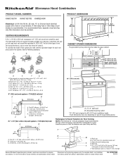
... are not followed. W10247296B Table of Contents MICROWAVE HOOD COMBINATION SAFETY 1 INSTALLATION REQUIREMENTS 2 Tools and Parts 2 Remove Cardboard Template 2 Location Requirements 2 Product Dimensions 3 Electrical Requirements 3 INSTALLATION INSTRUCTIONS 4 Remove Mounting Plate 4 Rotate Blower Motor 4 Locate Wall Stud(s ...: DANGER You can be killed or seriously injured if you don't follow instructions. All safety messages will follow instructions. These installation instructions cover different models. The appearance of your appliance. WARNING You can be ...
... are not followed. W10247296B Table of Contents MICROWAVE HOOD COMBINATION SAFETY 1 INSTALLATION REQUIREMENTS 2 Tools and Parts 2 Remove Cardboard Template 2 Location Requirements 2 Product Dimensions 3 Electrical Requirements 3 INSTALLATION INSTRUCTIONS 4 Remove Mounting Plate 4 Rotate Blower Motor 4 Locate Wall Stud(s ...: DANGER You can be killed or seriously injured if you don't follow instructions. All safety messages will follow instructions. These installation instructions cover different models. The appearance of your appliance. WARNING You can be ...
Installation Guide
Page 2
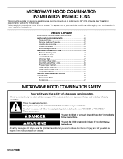
... installation dimensions. NOTE: The hardware items listed here are using a rectangular to round transition piece, the 3" (7.6 cm) clearance needs to make sure there is for cooking. Damper assembly (for 1/4" x 2" lag screws ■ Scissors ■ 1½" (3.8 cm) diam. See User Instructions.)...roof venting) Not Shown: Upper cabinet template Mounting plate (attached to Round Transition" illustration in "Venting Design Specifications" section. 2 See "Installation Dimensions" illustration. ■ Minimum one 2" x 4" (50.8 x 101.6 mm) wood wall stud and minimum 3/8" (10 mm)...
... installation dimensions. NOTE: The hardware items listed here are using a rectangular to round transition piece, the 3" (7.6 cm) clearance needs to make sure there is for cooking. Damper assembly (for 1/4" x 2" lag screws ■ Scissors ■ 1½" (3.8 cm) diam. See User Instructions.)...roof venting) Not Shown: Upper cabinet template Mounting plate (attached to Round Transition" illustration in "Venting Design Specifications" section. 2 See "Installation Dimensions" illustration. ■ Minimum one 2" x 4" (50.8 x 101.6 mm) wood wall stud and minimum 3/8" (10 mm)...
Installation Guide
Page 3
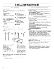
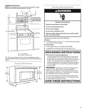
... qualified electrician or serviceman if the grounding instructions are not completely understood, or if doubt exists as to follow these instructions can result in death, fire, or electrical shock. The microwave oven is properly installed and grounded. See "Electrical Requirements" section....8260;₄m") 29⁷⁄₈" (76.0 cm) GROUNDING INSTRUCTIONS ■ For all governing codes and ordinances. If the power supply cord is typical for the electric current. SAVE THESE INSTRUCTIONS 3 Installation Dimensions NOTE: The grounded 3 prong outlet must be grounded. ...
... qualified electrician or serviceman if the grounding instructions are not completely understood, or if doubt exists as to follow these instructions can result in death, fire, or electrical shock. The microwave oven is properly installed and grounded. See "Electrical Requirements" section....8260;₄m") 29⁷⁄₈" (76.0 cm) GROUNDING INSTRUCTIONS ■ For all governing codes and ordinances. If the power supply cord is typical for the electric current. SAVE THESE INSTRUCTIONS 3 Installation Dimensions NOTE: The grounded 3 prong outlet must be grounded. ...
Installation Guide
Page 4
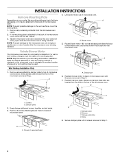
...with 2 screws removed in Step 3. 7. Remove any remaining contents from the microwave oven cavity. 2. Make sure damper plate tabs are using recirculation installation. A A. Screws (in recessed holes) D A. Damper plate tabs D. Rotate blower motor 180° so that door does not swing open ...removed in Step 1. 4 Remove screws attaching damper plate to back of microwave oven exterior. Screws B. Wall Venting Installation Only 1. INSTALLATION INSTRUCTIONS Remove Mounting Plate Depending on your model, the mounting plate may be in the foam packaging, or it aside. 3.
...with 2 screws removed in Step 3. 7. Remove any remaining contents from the microwave oven cavity. 2. Make sure damper plate tabs are using recirculation installation. A A. Screws (in recessed holes) D A. Damper plate tabs D. Rotate blower motor 180° so that door does not swing open ...removed in Step 1. 4 Remove screws attaching damper plate to back of microwave oven exterior. Screws B. Wall Venting Installation Only 1. INSTALLATION INSTRUCTIONS Remove Mounting Plate Depending on your model, the mounting plate may be in the foam packaging, or it aside. 3.
Installation Guide
Page 10
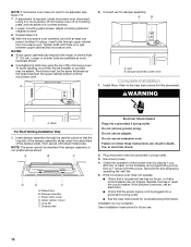
... be adjusted, skip steps 7-9. 7. A B A. Vent B. Damper assembly (under the raised tabs of the damper assembly slides under vent) Complete Installation 1. Refer to the User Instructions for future use. 10 WARNING A. A B C D E F A. Raised tabs B. Damper assembly C. Sheet metal screw D. Upper cabinet cutout E. Long tab F. Do not use an extension cord. Check ... 8. If the microwave oven does not operate: ■ Check that a household fuse has not blown, or that the long tab of the damper plate. Save Installation Instructions for filter placement.
... be adjusted, skip steps 7-9. 7. A B A. Vent B. Damper assembly (under the raised tabs of the damper assembly slides under vent) Complete Installation 1. Refer to the User Instructions for future use. 10 WARNING A. A B C D E F A. Raised tabs B. Damper assembly C. Sheet metal screw D. Upper cabinet cutout E. Long tab F. Do not use an extension cord. Check ... 8. If the microwave oven does not operate: ■ Check that a household fuse has not blown, or that the long tab of the damper plate. Save Installation Instructions for filter placement.
Installation Guide
Page 12
...Assembly ■ Mounting Plate ■ Upper Cabinet Template ■ Mounting Screw Kit (includes parts A-G in "Parts Supplied" in the User Instructions. You will need , add the equivalent lengths of the microwave oven. See "Recommended Standard Fittings" section for either type of available replacement... keep the damper from your model number located on the front facing of the installation hardware needs to be found on the front frame of each vent piece used in the User Instructions. Accessories Filler Panel Kits are available from sticking. Two 90° elbows = 20 ft ...
...Assembly ■ Mounting Plate ■ Upper Cabinet Template ■ Mounting Screw Kit (includes parts A-G in "Parts Supplied" in the User Instructions. You will need , add the equivalent lengths of the microwave oven. See "Recommended Standard Fittings" section for either type of available replacement... keep the damper from your model number located on the front facing of the installation hardware needs to be found on the front frame of each vent piece used in the User Instructions. Accessories Filler Panel Kits are available from sticking. Two 90° elbows = 20 ft ...
Use & Care Guide
Page 1
... shock, fire, injury to persons, or exposure to excessive microwave energy: ■ Install or locate the microwave oven only in the provided Installation Instructions. for Choosing KitchenAid® Appliances. See "GROUNDING INSTRUCTIONS" found in this section and in accordance with the provided Installation Instructions. ■ Read all safety messages. You can be followed, including the following: WARNING...
... shock, fire, injury to persons, or exposure to excessive microwave energy: ■ Install or locate the microwave oven only in the provided Installation Instructions. for Choosing KitchenAid® Appliances. See "GROUNDING INSTRUCTIONS" found in this section and in accordance with the provided Installation Instructions. ■ Read all safety messages. You can be followed, including the following: WARNING...
Use & Care Guide
Page 3
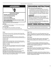
...Touch the Options or Setup control to unlock control. Electrical Requirements WARNING GROUNDING INSTRUCTIONS Electrical Shock Hazard Plug into an outlet that is too short, have a qualified electrician or serviceman install an outlet near the microwave oven. Do not remove ground prong. Do...A.M. The microwave oven is properly grounded. WARNING: Improper use an extension cord. Consult a qualified electrician or serviceman if the grounding instructions are not completely understood, or if doubt exists as cooling fan during any cook function. Settings Clock The Clock is a 12...
...Touch the Options or Setup control to unlock control. Electrical Requirements WARNING GROUNDING INSTRUCTIONS Electrical Shock Hazard Plug into an outlet that is too short, have a qualified electrician or serviceman install an outlet near the microwave oven. Do not remove ground prong. Do...A.M. The microwave oven is properly grounded. WARNING: Improper use an extension cord. Consult a qualified electrician or serviceman if the grounding instructions are not completely understood, or if doubt exists as cooling fan during any cook function. Settings Clock The Clock is a 12...
Use & Care Guide
Page 5
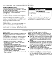
... (on the underside of any cycle, "ADD MORE TIME 0:00" appears in food poisoning or sickness. See "Settings" section to follow label instructions on the vent grille, tilt the grille forward, and lift it out. Close bulb cover, replace vent grille, and secure with your model.... light: The cavity light bulb is cool. Hot cooked food can be replaced about every 6 months, or as prompted by filter status indicator. Installing/Replacing Filters and Light Bulbs NOTE: A filter status indicator (on the vent grille, tilt the grille forward, lift it is used by arcing ...
... (on the underside of any cycle, "ADD MORE TIME 0:00" appears in food poisoning or sickness. See "Settings" section to follow label instructions on the vent grille, tilt the grille forward, and lift it out. Close bulb cover, replace vent grille, and secure with your model.... light: The cavity light bulb is cool. Hot cooked food can be replaced about every 6 months, or as prompted by filter status indicator. Installing/Replacing Filters and Light Bulbs NOTE: A filter status indicator (on the vent grille, tilt the grille forward, lift it is used by arcing ...
Use & Care Guide
Page 7
... products not approved by the customer. Service calls to correct the installation of your authorized KitchenAid dealer to determine if another warranty applies. 9/07 7 Major appliances with original model/serial numbers that is contrary to published user or operator instructions and/or installation instructions. 4. IMPLIED WARRANTIES, INCLUDING WARRANTIES OF MERCHANTABILITY OR FITNESS FOR A PARTICULAR PURPOSE...
... products not approved by the customer. Service calls to correct the installation of your authorized KitchenAid dealer to determine if another warranty applies. 9/07 7 Major appliances with original model/serial numbers that is contrary to published user or operator instructions and/or installation instructions. 4. IMPLIED WARRANTIES, INCLUDING WARRANTIES OF MERCHANTABILITY OR FITNESS FOR A PARTICULAR PURPOSE...


