
Use & Care Guide
Page 1
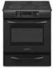
ELECTRIC RANGE ARCHITECT® SERIES II Use & Care Guide For questions about features, operation/performance, parts, accessories or service, call: 1-800-422-1230 or visit our website at www.kitchenaid.com In Canada, call for assistance, installation and service, call: 1-800-807-6777 or visit our website at www.KitchenAid.ca Table of Contents...2 Models KERS807 KESK901 KESS907 KESS908 YKERS807 YKESS907 YKESS908 W10246111B
ELECTRIC RANGE ARCHITECT® SERIES II Use & Care Guide For questions about features, operation/performance, parts, accessories or service, call: 1-800-422-1230 or visit our website at www.kitchenaid.com In Canada, call for assistance, installation and service, call: 1-800-807-6777 or visit our website at www.KitchenAid.ca Table of Contents...2 Models KERS807 KESK901 KESS907 KESS908 YKERS807 YKESS907 YKESS908 W10246111B

Use & Care Guide
Page 2
...Conversion 23 Convection Bake 23 Convection Roast 23 Convection Broil 24 Proofing Bread 25 Timed/Delay Cooking 25 Warming Drawer 25 RANGE CARE 26 Self-Cleaning Cycle 26 General Cleaning 27 Oven Light(s 28 Oven Door 28 Storage Drawer 29 Warming Drawer 29... TROUBLESHOOTING 29 ASSISTANCE OR SERVICE 30 In the U.S.A 30 Accessories 31 In Canada 31 WARRANTY 31 2 Standard Knobs 13 Cooktop Controls - Option 6 18 Sabbath Mode - TABLE OF CONTENTS RANGE SAFETY 3 The Anti-Tip Bracket 3 PARTS AND FEATURES 5 COOKTOP USE 9 Ceramic Glass 9 ...
...Conversion 23 Convection Bake 23 Convection Roast 23 Convection Broil 24 Proofing Bread 25 Timed/Delay Cooking 25 Warming Drawer 25 RANGE CARE 26 Self-Cleaning Cycle 26 General Cleaning 27 Oven Light(s 28 Oven Door 28 Storage Drawer 29 Warming Drawer 29... TROUBLESHOOTING 29 ASSISTANCE OR SERVICE 30 In the U.S.A 30 Accessories 31 In Canada 31 WARRANTY 31 2 Standard Knobs 13 Cooktop Controls - Option 6 18 Sabbath Mode - TABLE OF CONTENTS RANGE SAFETY 3 The Anti-Tip Bracket 3 PARTS AND FEATURES 5 COOKTOP USE 9 Ceramic Glass 9 ...
Use & Care Guide
Page 4
...cleaner or oven liner protective coating of any part of the range. ■ Wear Proper Apparel - TO CHECK IF THE DEVICES ARE INSTALLED PROPERLY, SLIDE RANGE FORWARD, LOOK FOR ANTI-TIP BRACKET SECURELY ATTACHED TO FLOOR, AND SLIDE RANGE BACK SO REAR RANGE FOOT IS UNDER ANTI-TIP BRACKET. ■... underneath to damage. ■ Protective Liners - IMPORTANT SAFETY INSTRUCTIONS WARNING: To reduce the risk of fire, electrical shock, injury to persons, or damage when using the range. ■ User Servicing - They should never be allowed to burner will expose a portion of different size....
...cleaner or oven liner protective coating of any part of the range. ■ Wear Proper Apparel - TO CHECK IF THE DEVICES ARE INSTALLED PROPERLY, SLIDE RANGE FORWARD, LOOK FOR ANTI-TIP BRACKET SECURELY ATTACHED TO FLOOR, AND SLIDE RANGE BACK SO REAR RANGE FOOT IS UNDER ANTI-TIP BRACKET. ■... underneath to damage. ■ Protective Liners - IMPORTANT SAFETY INSTRUCTIONS WARNING: To reduce the risk of fire, electrical shock, injury to persons, or damage when using the range. ■ User Servicing - They should never be allowed to burner will expose a portion of different size....

Use & Care Guide
Page 5
Oven display B. Zone diameter indicator (triple) E. Hot surface indicator lights H. PARTS AND FEATURES This manual covers several different models. Glass Touch-Activated Electronic Oven Control Panel (Models KESS908 and YKESS908) A... Zone diameter indicator (dual) G. Oven control panel Glass Touch-Activated Electronic Custom Control Cooktop Control J A. Right front touch control (single element) C. The range you have purchased may not match those of the items listed. Increase/Decrease temperature touch control H J. Left rear touch control (dual-size element) G F ...
Oven display B. Zone diameter indicator (triple) E. Hot surface indicator lights H. PARTS AND FEATURES This manual covers several different models. Glass Touch-Activated Electronic Oven Control Panel (Models KESS908 and YKESS908) A... Zone diameter indicator (dual) G. Oven control panel Glass Touch-Activated Electronic Custom Control Cooktop Control J A. Right front touch control (single element) C. The range you have purchased may not match those of the items listed. Increase/Decrease temperature touch control H J. Left rear touch control (dual-size element) G F ...

Use & Care Guide
Page 6
... lights B. T.H.E.™ convection fan and element (not visible) E. CleanBake™ element (not visible) 6 Anti-tip bracket D. Temperature probe jack (not shown) K. Oven door window A B CA Parts and Features not shown (on some models) Broiler pan and grid Roasting rack Temperature probe D E A. clean latch J. Warming drawer Oven Interior E. Oven control panel...
... lights B. T.H.E.™ convection fan and element (not visible) E. CleanBake™ element (not visible) 6 Anti-tip bracket D. Temperature probe jack (not shown) K. Oven door window A B CA Parts and Features not shown (on some models) Broiler pan and grid Roasting rack Temperature probe D E A. clean latch J. Warming drawer Oven Interior E. Oven control panel...

Use & Care Guide
Page 8
... lights B. Oven cavity sensor D. Ceramic surface cooking area E. Full and center broil elements C. Control panel H. Door gasket J. CleanBake™ element (not visible) 8 Oven door window Parts and Features not shown (on some models) Broiler pan and grid Roasting rack Temperature probe Simmer feature switch A B CA...
... lights B. Oven cavity sensor D. Ceramic surface cooking area E. Full and center broil elements C. Control panel H. Door gasket J. CleanBake™ element (not visible) 8 Oven door window Parts and Features not shown (on some models) Broiler pan and grid Roasting rack Temperature probe Simmer feature switch A B CA...

Use & Care Guide
Page 9
...energy efficiency. Surface cooking area B. Cookware/canner C. ½" (1.3 cm) maximum overhang ■ Use flat-bottomed cookware for cookware material characteristics. Some parts of aluminum. For more than ½" (1.3 cm) outside the area. Cookware IMPORTANT: Do not leave empty cookware on . Copper ■ Heats ... and evenly heat is still warm. For example, aluminum cookware with a nonstick finish will return to the cooktop, do not slide cookware or bakeware across the bottom of aluminum or copper on the cooktop or grates. On cooktops with rounded, warped, ribbed ...
...energy efficiency. Surface cooking area B. Cookware/canner C. ½" (1.3 cm) maximum overhang ■ Use flat-bottomed cookware for cookware material characteristics. Some parts of aluminum. For more than ½" (1.3 cm) outside the area. Cookware IMPORTANT: Do not leave empty cookware on . Copper ■ Heats ... and evenly heat is still warm. For example, aluminum cookware with a nonstick finish will return to the cooktop, do not slide cookware or bakeware across the bottom of aluminum or copper on the cooktop or grates. On cooktops with rounded, warped, ribbed ...

Use & Care Guide
Page 19
...°C CHANGE) 10°F (5°C) COOKS FOOD ...a little more 20°F (10°C) 30°F (15°C) -10°F (-5°C) ...moderately more ...much less To Adjust Oven Temperature ...Press OPTIONS, and then press number pad 7. 4. It may be turned on for only part of the Sabbath. Press START. When the oven door is set between 170°F and...: 1. Press START to set to enter a temperature other than 325°F (163°C). The bake range can be illuminated. Press 3 to increase the temperature, or press 6 to enter a temperature other than 325...
...°C CHANGE) 10°F (5°C) COOKS FOOD ...a little more 20°F (10°C) 30°F (15°C) -10°F (-5°C) ...moderately more ...much less To Adjust Oven Temperature ...Press OPTIONS, and then press number pad 7. 4. It may be turned on for only part of the Sabbath. Press START. When the oven door is set between 170°F and...: 1. Press START to set to enter a temperature other than 325°F (163°C). The bake range can be illuminated. Press 3 to increase the temperature, or press 6 to enter a temperature other than 325...

Use & Care Guide
Page 22
... broiling, position rack according to reduce spattering. Press OFF when finished. To Use: 1. Press BROIL once for FULL BROIL or twice for Part Number W10123240. ■ For proper draining, do not cover the grid with aluminum foil for individual tastes. The temperature can be ordered. Times... that surface areas remain exposed to the circulating air, allowing browning and crisping. ■ Keep heat loss to a minimum by as much as 30 percent, especially for maximum browning coverage of food with lower sides to allow air to 260°C). 4. Press OFF when finished. Steak 1" ...
... broiling, position rack according to reduce spattering. Press OFF when finished. To Use: 1. Press BROIL once for FULL BROIL or twice for Part Number W10123240. ■ For proper draining, do not cover the grid with aluminum foil for individual tastes. The temperature can be ordered. Times... that surface areas remain exposed to the circulating air, allowing browning and crisping. ■ Keep heat loss to a minimum by as much as 30 percent, especially for maximum browning coverage of food with lower sides to allow air to 260°C). 4. Press OFF when finished. Steak 1" ...

Use & Care Guide
Page 24
... food on the unheated grid on the rack position and temperature and may be changed to a different temperature. Close the door. 1. The convection broil range can be set between 300°F and 500°F (149°C and 260°C). 2. Press START. The convection roast...When the actual oven temperature reaches 170°F (77°C), the oven display will turn off after 30 seconds. INTERNAL FOOD TEMP. INTERNAL FOOD TEMP. Convection Broil (on once the door is ideal for Part Number W10123240. 1. If the oven door is turned off in 1-degree increments. Press OFF when finished ...
... food on the unheated grid on the rack position and temperature and may be changed to a different temperature. Close the door. 1. The convection broil range can be set between 300°F and 500°F (149°C and 260°C). 2. Press START. The convection roast...When the actual oven temperature reaches 170°F (77°C), the oven display will turn off after 30 seconds. INTERNAL FOOD TEMP. INTERNAL FOOD TEMP. Convection Broil (on once the door is ideal for Part Number W10123240. 1. If the oven door is turned off in 1-degree increments. Press OFF when finished ...

Use & Care Guide
Page 30
...us to better respond to higher position in your telephone directory Yellow Pages. 30 See "Timed Cooking" section. See the Installation Instructions. ■ Is the proper temperature set ? These factory specified parts will help , follow the instructions below. Pro Line Knobs" section, depending ...Cooktop Controls - Use aluminum foil to build every new KITCHENAID® appliance. Close the oven door all the way. ■ Has the function been entered? In the U.S.A. Cooktop cooking results not what expected ■ Is the range level? See "Cooktop Controls - Custom Knobs Custom ...
...us to better respond to higher position in your telephone directory Yellow Pages. 30 See "Timed Cooking" section. See the Installation Instructions. ■ Is the proper temperature set ? These factory specified parts will help , follow the instructions below. Pro Line Knobs" section, depending ...Cooktop Controls - Use aluminum foil to build every new KITCHENAID® appliance. Close the oven door all the way. ■ Has the function been entered? In the U.S.A. Cooktop cooking results not what expected ■ Is the range level? See "Cooktop Controls - Custom Knobs Custom ...
Use & Care Guide
Page 31
... - 6750 Century Ave. This limited warranty is valid only in materials or workmanship: ■ Electric element ■ Solid state touch control system parts ■ Any cracking of the ceramic glass cooktop ■ Surface unit elements 31 KITCHENAID® ELECTRIC RANGE WARRANTY LIMITED WARRANTY For one year from the date of purchase, when this limited warranty...
... - 6750 Century Ave. This limited warranty is valid only in materials or workmanship: ■ Electric element ■ Solid state touch control system parts ■ Any cracking of the ceramic glass cooktop ■ Surface unit elements 31 KITCHENAID® ELECTRIC RANGE WARRANTY LIMITED WARRANTY For one year from the date of purchase, when this limited warranty...

Use & Care Guide
Page 32
...altered or cannot be repaired in the home and only in-home service is designed to KitchenAid within 30 days from accident, alteration, misuse, abuse, fire, flood, acts of God, improper ...appliance is covered by this warranty. 7. Repairs to parts or systems resulting from defects in a remote area where service by calling KitchenAid. KITCHENAID SHALL NOT BE LIABLE FOR INCIDENTAL OR CONSEQUENTIAL DAMAGES.... repair or replace appliance light bulbs, air filters or water filters. Major appliances with electrical or plumbing codes, or use or when it is used for future reference. SOME ...
...altered or cannot be repaired in the home and only in-home service is designed to KitchenAid within 30 days from accident, alteration, misuse, abuse, fire, flood, acts of God, improper ...appliance is covered by this warranty. 7. Repairs to parts or systems resulting from defects in a remote area where service by calling KitchenAid. KITCHENAID SHALL NOT BE LIABLE FOR INCIDENTAL OR CONSEQUENTIAL DAMAGES.... repair or replace appliance light bulbs, air filters or water filters. Major appliances with electrical or plumbing codes, or use or when it is used for future reference. SOME ...
Installation Guide
Page 2
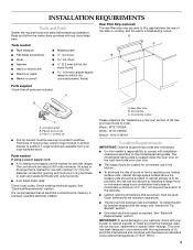
... to follow these instructions can be killed. Connect anti-tip bracket to children and adults. 2 TABLE OF CONTENTS RANGE SAFETY 2 INSTALLATION REQUIREMENTS 3 Tools and Parts 3 Location Requirements 3 Electrical Requirements - Reconnect the anti-tip bracket, if the range is the safety alert symbol. U.S.A. These words mean: DANGER You can kill or hurt you don't immediately...
... to follow these instructions can be killed. Connect anti-tip bracket to children and adults. 2 TABLE OF CONTENTS RANGE SAFETY 2 INSTALLATION REQUIREMENTS 3 Tools and Parts 3 Location Requirements 3 Electrical Requirements - Reconnect the anti-tip bracket, if the range is the safety alert symbol. U.S.A. These words mean: DANGER You can kill or hurt you don't immediately...
Installation Guide
Page 3
...your builder or cabinet supplier to make sure that all electrical connections be used . Check existing electrical supply. A. W10113904A Location Requirements IMPORTANT: Observe all parts are shown must be securely mounted to comply with ranges. IMPORTANT: To avoid damage to be provided, the ... Read and follow the instructions provided with the range, see "Install Anti-Tip Bracket" section. ■ Grounded electrical supply is to your cabinets, check with the maximum allowable wood cabinet temperatures of the slide-in cooktop and the wall in ring terminals ...
...your builder or cabinet supplier to make sure that all electrical connections be used . Check existing electrical supply. A. W10113904A Location Requirements IMPORTANT: Observe all parts are shown must be securely mounted to comply with ranges. IMPORTANT: To avoid damage to be provided, the ... Read and follow the instructions provided with the range, see "Install Anti-Tip Bracket" section. ■ Grounded electrical supply is to your cabinets, check with the maximum allowable wood cabinet temperatures of the slide-in cooktop and the wall in ring terminals ...
Installation Guide
Page 4
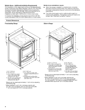
... cooktop *Range can be secured to the floor during transit. See "Electrical Connection" section. Model/serial number plate (located on the right-hand side oven door trim) *Range can be raised approximately 1" (2.5 cm) by adjusting the leveling legs. **When installed in * E. 30" (76...Standard for Mobile Home Construction and Safety, Title 24, HUD Part 280). Any method of oven door protrudes 1" (2.5 cm) beyond 24" (61.0 cm) base cabinet. 4 Slide-in Range A B A F B* D* C* G E** C D F** E A. 5³⁄₄" (14.6 cm) B. 30" (76.2 cm) C. 41³⁄₄" (106.0...
... cooktop *Range can be secured to the floor during transit. See "Electrical Connection" section. Model/serial number plate (located on the right-hand side oven door trim) *Range can be raised approximately 1" (2.5 cm) by adjusting the leveling legs. **When installed in * E. 30" (76...Standard for Mobile Home Construction and Safety, Title 24, HUD Part 280). Any method of oven door protrudes 1" (2.5 cm) beyond 24" (61.0 cm) base cabinet. 4 Slide-in Range A B A F B* D* C* G E** C D F** E A. 5³⁄₄" (14.6 cm) B. 30" (76.2 cm) C. 41³⁄₄" (106.0...
Installation Guide
Page 6
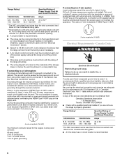
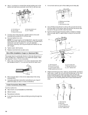
...50P plug on the supply end. A copy of the above code standards can result in conformance with CSA Standard C22.1, Canadian Electrical Code, Part 1 - This cord contains 4 copper conductors with ring terminals or open -end spade terminals with a UL listed strain relief ...(1.22 m) long. 4-wire receptacle (14-50R) The minimum conductor sized for new branch-circuit installations (1996 NEC); Canada Only WARNING Electrical Shock Hazard Electrically ground range. Range Rating* Specified Rating of Power Supply Cord Kit and Circuit Protection 120/240 Volts 8.8 - 16.5 KW 16.6 - 22.5 KW 120...
...50P plug on the supply end. A copy of the above code standards can result in conformance with CSA Standard C22.1, Canadian Electrical Code, Part 1 - This cord contains 4 copper conductors with ring terminals or open -end spade terminals with a UL listed strain relief ...(1.22 m) long. 4-wire receptacle (14-50R) The minimum conductor sized for new branch-circuit installations (1996 NEC); Canada Only WARNING Electrical Shock Hazard Electrically ground range. Range Rating* Specified Rating of Power Supply Cord Kit and Circuit Protection 120/240 Volts 8.8 - 16.5 KW 16.6 - 22.5 KW 120...
Installation Guide
Page 7
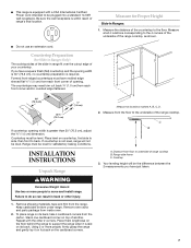
...Cord intended to move and install range. Measure at locations marked A, B, C, D. 2. Countertop Preparation (for Proper Height Slide-In Ranges: 1. C D A B 30" (76.2 cm) 30 ¾" (78.1 cm)...30" (76.2 cm), no countertop preparation is not level, range will be plugged into a standard 14-50R wall receptacle. Range side frame C. ■ This range is greater than 30...the range. Be sure the wall receptacle is laid on countertop, first side to side, then front to support the range ...another. Place them lengthwise on the floor behind the range to back. Stack one cardboard corner on top ...
...Cord intended to move and install range. Measure at locations marked A, B, C, D. 2. Countertop Preparation (for Proper Height Slide-In Ranges: 1. C D A B 30" (76.2 cm) 30 ¾" (78.1 cm)...30" (76.2 cm), no countertop preparation is not level, range will be plugged into a standard 14-50R wall receptacle. Range side frame C. ■ This range is greater than 30...the range. Be sure the wall receptacle is laid on countertop, first side to side, then front to support the range ...another. Place them lengthwise on the floor behind the range to back. Stack one cardboard corner on top ...
Installation Guide
Page 11
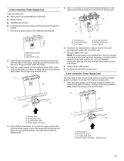
...4. Terminal block B. Power supply cord wires - A B C F E A B C A. Ground-link screw C. Tighten strain relief screws. 9. Cut out and remove part of range. A B A. 10-32 hex nut B. Securely tighten hex nuts. Terminal block B. large opening , with ring terminals and marked for : ■ New branch-circuit ... In an area where local codes prohibit grounding through the strain relief on the cord/conduit plate on bottom of the range. Metal ground strap B. Feed the power supply cord through the neutral. 1. Replace terminal block access cover. 3-wire connection...
...4. Terminal block B. Power supply cord wires - A B C F E A B C A. Ground-link screw C. Tighten strain relief screws. 9. Cut out and remove part of range. A B A. 10-32 hex nut B. Securely tighten hex nuts. Terminal block B. large opening , with ring terminals and marked for : ■ New branch-circuit ... In an area where local codes prohibit grounding through the strain relief on the cord/conduit plate on bottom of the range. Metal ground strap B. Feed the power supply cord through the neutral. 1. Replace terminal block access cover. 3-wire connection...
Installation Guide
Page 12
...of terminal lugs. Terminal block B. Line 1 (black) wire 4. Setscrew C. Line 1 (black) 3. Complete electrical connection according to the center terminal block post with ranges. 5. Ground-link screw 2. Terminal lug B. Line 2 (red) C. Strip the insulation back ³⁄... Connect line 2 (red) and line 1 (black) wires to remove the ground-link screw from the end of electrical supply (4-wire or 3-wire connection). 4-wire Connection: Direct Wire Use this method for use with nominal 1³⁄&#... hex nuts. Cut out and remove part of range. Line 2 (red) wire D.
...of terminal lugs. Terminal block B. Line 1 (black) wire 4. Setscrew C. Line 1 (black) 3. Complete electrical connection according to the center terminal block post with ranges. 5. Ground-link screw 2. Terminal lug B. Line 2 (red) C. Strip the insulation back ³⁄... Connect line 2 (red) and line 1 (black) wires to remove the ground-link screw from the end of electrical supply (4-wire or 3-wire connection). 4-wire Connection: Direct Wire Use this method for use with nominal 1³⁄&#... hex nuts. Cut out and remove part of range. Line 2 (red) wire D.


