Use & Care Guide
Page 4
...steam burn. Areas near surface units. Heating elements should not be hot even though they have had sufficient time to cause burns. Absence of electric shock. Select utensils having flat bottoms large enough to a hot surface. s Glazed Cooking Utensils - Improper installation of these pans or bowls...cooking may become hot enough to cool. s Proper Installation - Only certain types of clothing. Do not repair or replace any part of the cooktop unless specifically recommended in Place - Some cleaners can produce noxious fumes if applied to cover the surface unit heating element....
...steam burn. Areas near surface units. Heating elements should not be hot even though they have had sufficient time to cause burns. Absence of electric shock. Select utensils having flat bottoms large enough to a hot surface. s Glazed Cooking Utensils - Improper installation of these pans or bowls...cooking may become hot enough to cool. s Proper Installation - Only certain types of clothing. Do not repair or replace any part of the cooktop unless specifically recommended in Place - Some cleaners can produce noxious fumes if applied to cover the surface unit heating element....
Use & Care Guide
Page 5
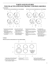
...; keep warm function; melt and hold function) B. Ceramic glass cooktop (stainless steel or painted metal trim on metal cabinet) 5 Control panel F. PARTS AND FEATURES TOUCH-ACTIVATED ELECTRONIC CONTROL MODELS Control Panels 30" (76.2 cm) Touch-Activated Electronic Control Models 36" (91.4 cm) Touch-Activated Electronic Control Models A B A B C C D G F E D H FE G A. melt and hold function...
...; keep warm function; melt and hold function) B. Ceramic glass cooktop (stainless steel or painted metal trim on metal cabinet) 5 Control panel F. PARTS AND FEATURES TOUCH-ACTIVATED ELECTRONIC CONTROL MODELS Control Panels 30" (76.2 cm) Touch-Activated Electronic Control Models 36" (91.4 cm) Touch-Activated Electronic Control Models A B A B C C D G F E D H FE G A. melt and hold function...
Use & Care Guide
Page 8
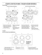
... C D A H A. Ceramic glass cooktop (stainless steel models have metal trim) B. Right rear surface cooking area E. Right front surface cooking area 8 E G. SMART KNOB MODELS Control Panels 30" (76.2 cm) Smart Knob Models 36" (91.4 cm) Smart Knob Models A B A B C F E D C A. Hot surface indicator light D. keep warm function; melt function...; Center rear surface cooking area (with triple-circuit element) H. keep warm function; melt function) F. Power on light G. PARTS AND FEATURES - Model and serial number plate (located underneath cooktop on metal cabinet)
... C D A H A. Ceramic glass cooktop (stainless steel models have metal trim) B. Right rear surface cooking area E. Right front surface cooking area 8 E G. SMART KNOB MODELS Control Panels 30" (76.2 cm) Smart Knob Models 36" (91.4 cm) Smart Knob Models A B A B C F E D C A. Hot surface indicator light D. keep warm function; melt function...; Center rear surface cooking area (with triple-circuit element) H. keep warm function; melt function) F. Power on light G. PARTS AND FEATURES - Model and serial number plate (located underneath cooktop on metal cabinet)

Use & Care Guide
Page 11
... front control knob F. Left rear control knob B. Right front control knob E. Ceramic glass cooktop (stainless steel models have metal trim) B. TRADITIONAL KNOB MODELS Control Panels 30" (76.2 cm) Traditional Knob Models 36" (91.4cm) Traditional Knob Models A B A B C F A. Hot surface indicator lights E. Right rear control knob (dual-circuit element) C. Center rear surface...
... front control knob F. Left rear control knob B. Right front control knob E. Ceramic glass cooktop (stainless steel models have metal trim) B. TRADITIONAL KNOB MODELS Control Panels 30" (76.2 cm) Traditional Knob Models 36" (91.4cm) Traditional Knob Models A B A B C F A. Hot surface indicator lights E. Right rear control knob (dual-circuit element) C. Center rear surface...
Use & Care Guide
Page 13
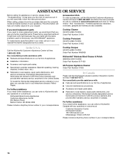
... cookware for the surface of white ceramic glass to appear to the cooktop and can be removed completely. s Do not use SINGLE (C): 1. Push in any part of a ruler across the cooktop. C A. Dropping a heavy or hard object onto the cooktop could break when the lid is normal for best heat conduction and...
... cookware for the surface of white ceramic glass to appear to the cooktop and can be removed completely. s Do not use SINGLE (C): 1. Push in any part of a ruler across the cooktop. C A. Dropping a heavy or hard object onto the cooktop could break when the lid is normal for best heat conduction and...
Use & Care Guide
Page 16
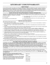
... provide assistance with any questions or concerns at 1-800-442-9991 and follow the instructions below. s Referrals to local dealers, repair parts distributors, and service companies. To locate the KitchenAid designated service company in your area, you can also look in your request. For further assistance If you need help us or...
... provide assistance with any questions or concerns at 1-800-442-9991 and follow the instructions below. s Referrals to local dealers, repair parts distributors, and service companies. To locate the KitchenAid designated service company in your area, you can also look in your request. For further assistance If you need help us or...
Use & Care Guide
Page 17
...9632; Electric element ■ Gas burners ■ Solid state touch control system parts ■ Any cracking of the rubber seal between the ceramic glass cooktop and porcelain edge ■ Any cracking due to correct house wiring or plumbing. 2. Repairs to KitchenAid within 30 days from... the date of purchase. 6. This limited warranty is valid only in an inaccessible location or is reported to parts or systems resulting from warranty coverage. 3. Service calls to correct ...
...9632; Electric element ■ Gas burners ■ Solid state touch control system parts ■ Any cracking of the rubber seal between the ceramic glass cooktop and porcelain edge ■ Any cracking due to correct house wiring or plumbing. 2. Repairs to KitchenAid within 30 days from... the date of purchase. 6. This limited warranty is valid only in an inaccessible location or is reported to parts or systems resulting from warranty coverage. 3. Service calls to correct ...
Installation Guide
Page 1
...étaire. Propriétaire : Conserver les instructions d'installation pour référence ultérieure. 8286066B ELECTRIC COOKTOP INSTALLATION INSTRUCTIONS INSTRUCTIONS D'INSTALLATION DE LA TABLE DE CUISSON ÉLECTRIQUE Table of Contents / Table des mati&#...232;res COOKTOP SAFETY 1 INSTALLATION REQUIREMENTS 2 Tools and Parts 2 Location Requirements 2 Electrical Requirements 3 INSTALLATION INSTRUCTIONS 4 Prepare Cooktop for Installation 4 Install Cooktop 5 Make Electrical Connection 6 Attach Cooktop to reduce the chance of others . Always read and...
...étaire. Propriétaire : Conserver les instructions d'installation pour référence ultérieure. 8286066B ELECTRIC COOKTOP INSTALLATION INSTRUCTIONS INSTRUCTIONS D'INSTALLATION DE LA TABLE DE CUISSON ÉLECTRIQUE Table of Contents / Table des mati&#...232;res COOKTOP SAFETY 1 INSTALLATION REQUIREMENTS 2 Tools and Parts 2 Location Requirements 2 Electrical Requirements 3 INSTALLATION INSTRUCTIONS 4 Prepare Cooktop for Installation 4 Install Cooktop 5 Make Electrical Connection 6 Attach Cooktop to reduce the chance of others . Always read and...
Installation Guide
Page 2
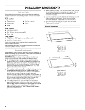
...in oven. Product Dimensions B A C A. 21 54.1 cm) B. 16 42.1 cm) 30 77.1 cm) 36 92.3 cm) C. 2⁷⁄₈" (7.3 cm) B A C A. 22¹⁄₈" (56.1 cm) B. 16 42.1 cm) 30 77.1 cm) 36 92.3 cm) C. 2⁷⁄₈" (7.3 cm) 2 When installing ...be avoided. Given dimensions are given with any tools listed here. Check existing electrical supply. See "Electrical Requirements" section. INSTALLATION REQUIREMENTS Tools and Parts Gather the required tools and parts before starting installation. Location Requirements Make sure you do not find this label,...
...in oven. Product Dimensions B A C A. 21 54.1 cm) B. 16 42.1 cm) 30 77.1 cm) 36 92.3 cm) C. 2⁷⁄₈" (7.3 cm) B A C A. 22¹⁄₈" (56.1 cm) B. 16 42.1 cm) 30 77.1 cm) 36 92.3 cm) C. 2⁷⁄₈" (7.3 cm) 2 When installing ...be avoided. Given dimensions are given with any tools listed here. Check existing electrical supply. See "Electrical Requirements" section. INSTALLATION REQUIREMENTS Tools and Parts Gather the required tools and parts before starting installation. Location Requirements Make sure you do not find this label,...
Installation Guide
Page 4
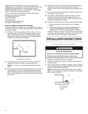
...Aluminum/copper connection must conform with edge. Model/serial number plate ■ Cooktops with the National Electrical Code, ANSI/NFPA 70-latest edition or CSA Standards C22.1-94, Canadian Electrical Code, Part 1 and C22.2 No. INSTALLATION INSTRUCTIONS A A. NOTE: The foam strip covers the underside ...to the added section of cooktop, flush with local codes and industry accepted wiring practices. NOTE: The 15" (38.1 cm) model series requires a 20-amp circuit. ■ The cooktop should be provided at the cooktop. ■ If the house has aluminum wiring follow...
...Aluminum/copper connection must conform with edge. Model/serial number plate ■ Cooktops with the National Electrical Code, ANSI/NFPA 70-latest edition or CSA Standards C22.1-94, Canadian Electrical Code, Part 1 and C22.2 No. INSTALLATION INSTRUCTIONS A A. NOTE: The foam strip covers the underside ...to the added section of cooktop, flush with local codes and industry accepted wiring practices. NOTE: The 15" (38.1 cm) model series requires a 20-amp circuit. ■ The cooktop should be provided at the cooktop. ■ If the house has aluminum wiring follow...
Installation Guide
Page 8
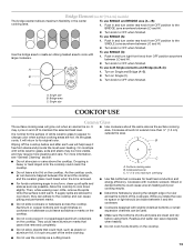
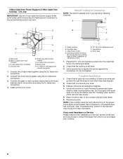
...8 For more information, see which step was skipped. 2. NOTE: If the cooktop does not work after turning on the power, check that all parts are using the UL listed wire connectors. 3. White wire (from cooktop) D. Do not overtighten. Bare or green wire from cooktop C. 3-wire cable... in the junction box using the UL listed wire connectors. 2. UL listed or CSA approved conduit connector 1. Check that the cooktop is an extra part, go back through the steps to see the "Cooktop Care" section of clamping screws) E. 2½" (6.4 cm) clamping screw F. See "Troubleshooting...
...8 For more information, see which step was skipped. 2. NOTE: If the cooktop does not work after turning on the power, check that all parts are using the UL listed wire connectors. 3. White wire (from cooktop) D. Do not overtighten. Bare or green wire from cooktop C. 3-wire cable... in the junction box using the UL listed wire connectors. 2. UL listed or CSA approved conduit connector 1. Check that the cooktop is an extra part, go back through the steps to see the "Cooktop Care" section of clamping screws) E. 2½" (6.4 cm) clamping screw F. See "Troubleshooting...


