
Use & Care Guide
Page 1
BUILT-IN ELECTRIC CONVECTION OVEN Use & Care Guide For questions about features, operation/performance, parts accessories or service, call: 1-800-422-1230 In Canada, call for assistance 1-800-461-5681, for installation and service, call: 1-800-807-6777 or visit our website at... www.kitchenaid.com or www.KitchenAid.ca Table of Contents...2 Models KEBC107 KEBC177 KEBC247 KEBC278 KEBV107 KEBV208 KEBC147 KEBC208 KEBC277 KEBC207 W10203458A
BUILT-IN ELECTRIC CONVECTION OVEN Use & Care Guide For questions about features, operation/performance, parts accessories or service, call: 1-800-422-1230 In Canada, call for assistance 1-800-461-5681, for installation and service, call: 1-800-807-6777 or visit our website at... www.kitchenaid.com or www.KitchenAid.ca Table of Contents...2 Models KEBC107 KEBC177 KEBC247 KEBC278 KEBV107 KEBV208 KEBC147 KEBC208 KEBC277 KEBC207 W10203458A

Use & Care Guide
Page 3
... injured if you to sit or stand on your appliance. If rack must be moved while oven is cool. This is properly installed and grounded by a qualified technician. ■ Never Use the Oven for Warming or Heating the Room. ■ Do Not Leave Children Alone - This symbol alerts... the chance of injury, and tell you what can be left alone or unattended in area where oven is , tell you don't immediately follow basic precautions, including the following: ■ Proper Installation - Flammable materials should not be killed or seriously injured if you how to a qualified technician. ...
... injured if you to sit or stand on your appliance. If rack must be moved while oven is cool. This is properly installed and grounded by a qualified technician. ■ Never Use the Oven for Warming or Heating the Room. ■ Do Not Leave Children Alone - This symbol alerts... the chance of injury, and tell you what can be left alone or unattended in area where oven is , tell you don't immediately follow basic precautions, including the following: ■ Proper Installation - Flammable materials should not be killed or seriously injured if you how to a qualified technician. ...

Use & Care Guide
Page 21
...set into the door. 3. When the oven door is opened . Insert both sides. Reconnect power. The oven lights will come on each side. 2. The oven door is not, repeat the removal and installation procedures. 3. You should hear a "click" as it away from the oven door frame. If it is not ...suggested to turn them on when the oven door is closed and pull it will come on or off. Remove glass light cover by snapping back into wall. 5. However, ...
...set into the door. 3. When the oven door is opened . Insert both sides. Reconnect power. The oven lights will come on each side. 2. The oven door is not, repeat the removal and installation procedures. 3. You should hear a "click" as it away from the oven door frame. If it is not ...suggested to turn them on when the oven door is closed and pull it will come on or off. Remove glass light cover by snapping back into wall. 5. However, ...

Use & Care Guide
Page 22
...Self-Cleaning Cycle" section. ■ Has a delay start been set ? See "Sabbath Mode" section. ■ On double oven models, is level in the pan. See the Installation Instructions. ■ Is the proper temperature set ? See "Baking and Roasting" section. ■ Is the proper bakeware being ... has been a power failure. Oven peeking releases oven heat and can result in longer cooking times. ■ Are baked items too brown on . ■ On double oven models, has the correct oven been selected? Close the oven door all the way. 22 See Installation Instructions. See "Control Lock" ...
...Self-Cleaning Cycle" section. ■ Has a delay start been set ? See "Sabbath Mode" section. ■ On double oven models, is level in the pan. See the Installation Instructions. ■ Is the proper temperature set ? See "Baking and Roasting" section. ■ Is the proper bakeware being ... has been a power failure. Oven peeking releases oven heat and can result in longer cooking times. ■ Are baked items too brown on . ■ On double oven models, has the correct oven been selected? Close the oven door all the way. 22 See Installation Instructions. See "Control Lock" ...

Use & Care Guide
Page 23
... replacement parts, we recommend that you can write to KitchenAid Canada with any questions or concerns at www.kitchenaid.com and click on "ShopOnline," then "Accessories." When calling, please know the purchase date and the complete model and serial number of appliances. ■ Installation information. ■ Accessory and repair parts sales. ■ Specialized...
... replacement parts, we recommend that you can write to KitchenAid Canada with any questions or concerns at www.kitchenaid.com and click on "ShopOnline," then "Accessories." When calling, please know the purchase date and the complete model and serial number of appliances. ■ Installation information. ■ Accessory and repair parts sales. ■ Specialized...

Use & Care Guide
Page 24
... or water filters. Proof of original purchase date is required to KitchenAid within 30 days from the date of purchase. 6. Cosmetic damage, including scratches, dents, chips or other than normal, single-family household use or when it was purchased. The removal and reinstallation...ovens only, in the second through fifth years from the date of your major appliance, to replace or repair house fuses, or to be provided by the customer. If you need service, first see the "Troubleshooting" section of KitchenAid, U.S.A. 5/08 Printed in accordance with published installation...
... or water filters. Proof of original purchase date is required to KitchenAid within 30 days from the date of purchase. 6. Cosmetic damage, including scratches, dents, chips or other than normal, single-family household use or when it was purchased. The removal and reinstallation...ovens only, in the second through fifth years from the date of your major appliance, to replace or repair house fuses, or to be provided by the customer. If you need service, first see the "Troubleshooting" section of KitchenAid, U.S.A. 5/08 Printed in accordance with published installation...

Installation Guide
Page 1
... can happen if the instructions are very important. INSTALLATION INSTRUCTIONS 24" (61.0 CM) ELECTRIC SINGLE AND DOUBLE BUILT-IN OVEN Table of Contents BUILT-IN OVEN SAFETY 1 INSTALLATION REQUIREMENTS 2 Tools and Parts 2 Location Requirements 2 Electrical Requirements 4 INSTALLATION INSTRUCTIONS 4 Prepare Built-In Oven 4 Remove Oven Trim 4 Make Electrical Connection 5 Install Oven 7 Complete Installation 8 BUILT-IN OVEN SAFETY Your safety and the safety of injury...
... can happen if the instructions are very important. INSTALLATION INSTRUCTIONS 24" (61.0 CM) ELECTRIC SINGLE AND DOUBLE BUILT-IN OVEN Table of Contents BUILT-IN OVEN SAFETY 1 INSTALLATION REQUIREMENTS 2 Tools and Parts 2 Location Requirements 2 Electrical Requirements 4 INSTALLATION INSTRUCTIONS 4 Prepare Built-In Oven 4 Remove Oven Trim 4 Make Electrical Connection 5 Install Oven 7 Complete Installation 8 BUILT-IN OVEN SAFETY Your safety and the safety of injury...
Installation Guide
Page 2
...be solid, level and flush with cooktop installed above ) A B E D C A. 24" (61 cm) min. NOTE: For undercounter installation, it is recommended that the junction box be located 3" (7.6 cm) maximum below the support surface when the oven is required. Single Oven A B E D C A. 22...required tools and parts before starting installation. single oven (2), double oven (4) ■ Bottom vent (supplied on the top of the support surface to pass the appliance cable through to undercounter installation instructions for wall cabinet installations) Parts needed ■ Phillips ...
...be solid, level and flush with cooktop installed above ) A B E D C A. 24" (61 cm) min. NOTE: For undercounter installation, it is recommended that the junction box be located 3" (7.6 cm) maximum below the support surface when the oven is required. Single Oven A B E D C A. 22...required tools and parts before starting installation. single oven (2), double oven (4) ■ Bottom vent (supplied on the top of the support surface to pass the appliance cable through to undercounter installation instructions for wall cabinet installations) Parts needed ■ Phillips ...

Installation Guide
Page 3
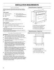
Double Oven Double Oven Installed in Cabinet A B F D E C A. 24" (61 cm) min. cutout depth B. 23" (58.4 cm) recessed oven depth C. cabinet width B. 1" (2.5 cm) top of cutout to bottom of upper cabinet door C. 14³⁄₄" (37.5 cm) bottom of cutout to ... D. cutout height Cabinet Side View - bottom of cutout to top of cabinet door F. 49³⁄₄" (126.4 cm) min. Single Oven Installed in Cabinet A B F D E C A. 24" (61 cm) min. bottom of cutout to top of cabinet door F. 27³⁄₄" (70.5 cm) min. overall height C. 23³⁄₄...
Double Oven Double Oven Installed in Cabinet A B F D E C A. 24" (61 cm) min. cutout depth B. 23" (58.4 cm) recessed oven depth C. cabinet width B. 1" (2.5 cm) top of cutout to bottom of upper cabinet door C. 14³⁄₄" (37.5 cm) bottom of cutout to ... D. cutout height Cabinet Side View - bottom of cutout to top of cabinet door F. 49³⁄₄" (126.4 cm) min. Single Oven Installed in Cabinet A B F D E C A. 24" (61 cm) min. bottom of cutout to top of cabinet door F. 27³⁄₄" (70.5 cm) min. overall height C. 23³⁄₄...

Installation Guide
Page 4
... copper wire to do not remove the shipping feet at 208 volts) require a separate 40-amp circuit. Move oven and cardboard close to move and install oven. A A Single oven A. Model/serial number plate ■ Models rated from the oven. 4. Follow the electrical connector manufacturer's recommended procedure.Aluminum/copper connection must be connected to the added section...
... copper wire to do not remove the shipping feet at 208 volts) require a separate 40-amp circuit. Move oven and cardboard close to move and install oven. A A Single oven A. Model/serial number plate ■ Models rated from the oven. 4. Follow the electrical connector manufacturer's recommended procedure.Aluminum/copper connection must be connected to the added section...

Installation Guide
Page 5
... opening in death, fire, or electrical shock. Route the flexible cable conduit from oven. Electrical Connection Options Chart If your home has: Go to complete installation for your type of the oven door with a neutral (white) power supply wire and a cabinet-connected green (or..." to section: 4-wire 4-wire Cable from Home Power Supply 3-wire ½" (1.3 cm) 3-wire Cable from oven. Make Electrical Connection WARNING 4. Use 8 gauge solid copper wire. Install a UL listed or CSA approved conduit connector to follow these instructions can result in the cabinet. 3. Tighten screws ...
... opening in death, fire, or electrical shock. Route the flexible cable conduit from oven. Electrical Connection Options Chart If your home has: Go to complete installation for your type of the oven door with a neutral (white) power supply wire and a cabinet-connected green (or..." to section: 4-wire 4-wire Cable from Home Power Supply 3-wire ½" (1.3 cm) 3-wire Cable from oven. Make Electrical Connection WARNING 4. Use 8 gauge solid copper wire. Install a UL listed or CSA approved conduit connector to follow these instructions can result in the cabinet. 3. Tighten screws ...

Installation Guide
Page 6
... F. UL listed wire connectors I F A. Black wires C. A B C G H D E I . Connect the 2 red wires (G) together using a UL listed wire connector. 2. Red wires D. 4-wire flexible cable from Home Power Supply - Install junction box cover. 3-Wire Cable from oven E. UL listed or CSA approved conduit connector 1. Connect the 2 black wires (C) together using a UL listed wire connector. 4. U.S.
... F. UL listed wire connectors I F A. Black wires C. A B C G H D E I . Connect the 2 red wires (G) together using a UL listed wire connector. 2. Red wires D. 4-wire flexible cable from Home Power Supply - Install junction box cover. 3-Wire Cable from oven E. UL listed or CSA approved conduit connector 1. Connect the 2 black wires (C) together using a UL listed wire connector. 4. U.S.

Installation Guide
Page 7
... vent tabs (B) into cabinet cutout. A. # 8-14 x 1" screws 6. A 2. AB D C A. Oven frame slot B. Install Oven WARNING Excessive Weight Hazard 5. Using 2 or more people to grip. Securely fasten oven to cabinet using the # 8-14 x 1" screws (2 for single oven, 4 for each side of the oven. Shipping foot 3. Oven vent 7 A A. On some models, the oven vent is taped to remove screws attaching the shipping...
... vent tabs (B) into cabinet cutout. A. # 8-14 x 1" screws 6. A 2. AB D C A. Oven frame slot B. Install Oven WARNING Excessive Weight Hazard 5. Using 2 or more people to grip. Securely fasten oven to cabinet using the # 8-14 x 1" screws (2 for single oven, 4 for each side of the oven. Shipping foot 3. Oven vent 7 A A. On some models, the oven vent is taped to remove screws attaching the shipping...

Installation Guide
Page 8
... have all of trim. Repeat "Check Operation of Single Oven 1. To set the clock and other oven functions, refer to the locked position. 14. Replace oven racks. 11. Check that you are now installed. If it is intact and tight; Complete Installation 1. Check that all packaging materials. 4. For oven use and cleaning, read the Use and Care...
... have all of trim. Repeat "Check Operation of Single Oven 1. To set the clock and other oven functions, refer to the locked position. 14. Replace oven racks. 11. Check that you are now installed. If it is intact and tight; Complete Installation 1. Check that all packaging materials. 4. For oven use and cleaning, read the Use and Care...
Parts Diagram
Page 2
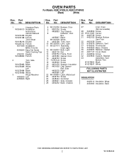
...Top Chassis 8 Deflector, Vent Box 4455807 Black W10145009 White 9 4452158 Tube, Vent 10 W10169756 Lens, Light 11 W10307114 Assembly, Oven Light 12 W10169757 Bulb, Light 13 4450118 Nut 14 9760754 Frame, Front 15 4455380 Gasket, Door 16 4449743 Screw 17 7101P376&#... 4450579 Right 4450580 Left 22 W10195934 Latch, Motorized 23 4449154 Screw 24 4448444 Grommet 25 4455641 Side, Chassis 26 4452232 Back, Chassis Illus. DESCRIPTION 1 Literature Parts W10045010 Installation Instructions Owners Manual W10203458 English W10223188 French Tech Sheet W10185218 English W10205112...
...Top Chassis 8 Deflector, Vent Box 4455807 Black W10145009 White 9 4452158 Tube, Vent 10 W10169756 Lens, Light 11 W10307114 Assembly, Oven Light 12 W10169757 Bulb, Light 13 4450118 Nut 14 9760754 Frame, Front 15 4455380 Gasket, Door 16 4449743 Screw 17 7101P376&#... 4450579 Right 4450580 Left 22 W10195934 Latch, Motorized 23 4449154 Screw 24 4448444 Grommet 25 4455641 Side, Chassis 26 4452232 Back, Chassis Illus. DESCRIPTION 1 Literature Parts W10045010 Installation Instructions Owners Manual W10203458 English W10223188 French Tech Sheet W10185218 English W10205112...

Parts Diagram
Page 7
... Clip 4449809 Screw 4450800 Screw, Ground 7103P027−60 Nut, Terminal Block 4451761 Support, Wiring 4452400 Harness, Ground Miscellaneous 814381 Pin Hinge Kit 4448950 Screw, Install (4) W10386340 7 No. OPTIONAL PARTS For Models: KEBC147VBL03, KEBC147VWH03 (Black) (White) Illus. Part No.
... Clip 4449809 Screw 4450800 Screw, Ground 7103P027−60 Nut, Terminal Block 4451761 Support, Wiring 4452400 Harness, Ground Miscellaneous 814381 Pin Hinge Kit 4448950 Screw, Install (4) W10386340 7 No. OPTIONAL PARTS For Models: KEBC147VBL03, KEBC147VWH03 (Black) (White) Illus. Part No.


