Use & Care Guide
Page 1
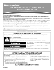
...shock, fire, injury to persons, or exposure to us at www.kitchenaid.com. IMPORTANT SAFETY INSTRUCTIONS When using electrical appliances basic safety precautions should not be heated in the provided Installation Instructions. Para obtener acceso a "Instrucciones para el usuario de la combinaci... are very important. Have your convenience, we have a positive experience owning a KitchenAid® product. SAVE THESE INSTRUCTIONS W10249655A This is important to excessive microwave energy: ■ Install or locate the microwave oven only in the shell and sealed containers - We ...
...shock, fire, injury to persons, or exposure to us at www.kitchenaid.com. IMPORTANT SAFETY INSTRUCTIONS When using electrical appliances basic safety precautions should not be heated in the provided Installation Instructions. Para obtener acceso a "Instrucciones para el usuario de la combinaci... are very important. Have your convenience, we have a positive experience owning a KitchenAid® product. SAVE THESE INSTRUCTIONS W10249655A This is important to excessive microwave energy: ■ Install or locate the microwave oven only in the shell and sealed containers - We ...
Use & Care Guide
Page 3
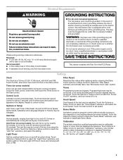
... shock. Scroll Speed Scroll speed of the FCC Rules. Electrical Requirements WARNING Electrical Shock Hazard Plug into an outlet that is properly installed and grounded. Do not use an extension cord. Observe all cord connected appliances: The microwave oven must be calibrated higher or lower... seconds until 2 tones sound and padlock icon appears in the display. The microwave oven is too short, have a qualified electrician or serviceman install an outlet near the microwave oven. WARNING: Improper use an adapter. Touch CLOCK, enter time, then touch CLOCK or the Start control. Repeat...
... shock. Scroll Speed Scroll speed of the FCC Rules. Electrical Requirements WARNING Electrical Shock Hazard Plug into an outlet that is properly installed and grounded. Do not use an extension cord. Observe all cord connected appliances: The microwave oven must be calibrated higher or lower... seconds until 2 tones sound and padlock icon appears in the display. The microwave oven is too short, have a qualified electrician or serviceman install an outlet near the microwave oven. WARNING: Improper use an adapter. Touch CLOCK, enter time, then touch CLOCK or the Start control. Repeat...
Use & Care Guide
Page 5
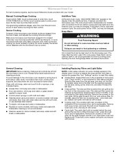
... be 100%, but may be programmed to replace the charcoal filter, and clean or replace the grease filter. Clean with convection) for at least 3 minutes. Installing/Replacing Filters and Light Bulbs NOTE: A filter status indicator (on some models), the sensor will be kept warm in the microwave oven detects moisture released...
... be 100%, but may be programmed to replace the charcoal filter, and clean or replace the grease filter. Clean with convection) for at least 3 minutes. Installing/Replacing Filters and Light Bulbs NOTE: A filter status indicator (on some models), the sensor will be kept warm in the microwave oven detects moisture released...
Use & Care Guide
Page 7
...not available. 9. You can write to or furnished with published installation instructions. 10. Proof of original purchase date is operated and maintained according to instructions attached to KitchenAid with the product, KitchenAid will pay for Factory Specified Parts for repairs. For assistance ...of your major appliance, to obtain service under these excluded circumstances shall be borne by a KitchenAid designated service company. Service calls to correct the installation of purchase, when this appliance is operated and maintained according to instructions attached to the ...
...not available. 9. You can write to or furnished with published installation instructions. 10. Proof of original purchase date is operated and maintained according to instructions attached to KitchenAid with the product, KitchenAid will pay for Factory Specified Parts for repairs. For assistance ...of your major appliance, to obtain service under these excluded circumstances shall be borne by a KitchenAid designated service company. Service calls to correct the installation of purchase, when this appliance is operated and maintained according to instructions attached to the ...
Installation Guide
Page 1
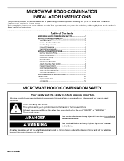
... others are not followed. Table of Contents MICROWAVE HOOD COMBINATION SAFETY 1 INSTALLATION REQUIREMENTS 2 Tools and Parts 2 Remove Cardboard Template 2 Location Requirements 2 Product Dimensions 3 Electrical Requirements 3 INSTALLATION INSTRUCTIONS 4 Remove Mounting Plate 4 Rotate Blower Motor 4 Locate Wall Stud...the potential hazard is, tell you how to Wall 8 Prepare Upper Cabinet 8 Install Damper Assembly 9 Install the Microwave Oven 9 Complete Installation 10 VENTING DESIGN SPECIFICATIONS 11 ASSISTANCE 12 Replacement Parts 12 Accessories 12 MICROWAVE HOOD ...
... others are not followed. Table of Contents MICROWAVE HOOD COMBINATION SAFETY 1 INSTALLATION REQUIREMENTS 2 Tools and Parts 2 Remove Cardboard Template 2 Location Requirements 2 Product Dimensions 3 Electrical Requirements 3 INSTALLATION INSTRUCTIONS 4 Remove Mounting Plate 4 Rotate Blower Motor 4 Locate Wall Stud...the potential hazard is, tell you how to Wall 8 Prepare Upper Cabinet 8 Install Damper Assembly 9 Install the Microwave Oven 9 Complete Installation 10 VENTING DESIGN SPECIFICATIONS 11 ASSISTANCE 12 Replacement Parts 12 Accessories 12 MICROWAVE HOOD ...
Installation Guide
Page 2
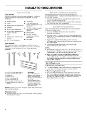
...Wall" part of packaging) Aluminum grease filters Charcoal filters (Depending on model, aluminum grease filter and charcoal filter may not be combined. See "Installation Dimensions" illustration. ■ Minimum one 2" x 4" (50.8 x 101.6 mm) wood wall stud and minimum 3/8" (10 mm) thickness ...Parts Supplied For reorder information, see "Replacement Parts" section. The piece inside upper cabinet. See "Electrical Requirements" section. For Roof Venting Installation Only: ■ If you are using a rectangular to round transition piece, the 3" (7.6 cm) clearance needs to exist above the...
...Wall" part of packaging) Aluminum grease filters Charcoal filters (Depending on model, aluminum grease filter and charcoal filter may not be combined. See "Installation Dimensions" illustration. ■ Minimum one 2" x 4" (50.8 x 101.6 mm) wood wall stud and minimum 3/8" (10 mm) thickness ...Parts Supplied For reorder information, see "Replacement Parts" section. The piece inside upper cabinet. See "Electrical Requirements" section. For Roof Venting Installation Only: ■ If you are using a rectangular to round transition piece, the 3" (7.6 cm) clearance needs to exist above the...
Installation Guide
Page 3
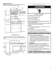
... inside the upper cabinet. Grounded 3 prong outlet *30" (76.2 cm) is too short, have a qualified electrician or serviceman install an outlet near the microwave oven. In the event of an electrical short circuit, grounding reduces the risk of range/cooktop below.... (76.2 cm) min. 30" (76.2 cm) typical* 12" (30.5 cm) min. 14" (35.6 cm) max. The microwave oven is properly installed and grounded. Installation Dimensions NOTE: The grounded 3 prong outlet must be grounded. See "Electrical Requirements" section. A. 2" x 4" wall stud B. Consult a qualified electrician or serviceman ...
... inside the upper cabinet. Grounded 3 prong outlet *30" (76.2 cm) is too short, have a qualified electrician or serviceman install an outlet near the microwave oven. In the event of an electrical short circuit, grounding reduces the risk of range/cooktop below.... (76.2 cm) min. 30" (76.2 cm) typical* 12" (30.5 cm) min. 14" (35.6 cm) max. The microwave oven is properly installed and grounded. Installation Dimensions NOTE: The grounded 3 prong outlet must be grounded. See "Electrical Requirements" section. A. 2" x 4" wall stud B. Consult a qualified electrician or serviceman ...
Installation Guide
Page 4
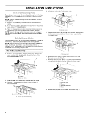
...screws attaching damper plate to the back of microwave oven. A B A. Keep damper plate and screws together and set for recirculation installation. A A. Secure damper plate with 2 screws removed in Step 3. 7. For wall or roof venting, changes must be made ... plate B. Slots 8. Remove any remaining contents from the microwave oven cavity. 2. Rotate Blower Motor The microwave oven is being handled. Wall Venting Installation Only 1. Reattach damper plate. Damper plate 2. Damper plate tabs D. If the mounting plate is attached to top of microwave oven. A A. Remove...
...screws attaching damper plate to the back of microwave oven. A B A. Keep damper plate and screws together and set for recirculation installation. A A. Secure damper plate with 2 screws removed in Step 3. 7. For wall or roof venting, changes must be made ... plate B. Slots 8. Remove any remaining contents from the microwave oven cavity. 2. Rotate Blower Motor The microwave oven is being handled. Wall Venting Installation Only 1. Reattach damper plate. Damper plate 2. Damper plate tabs D. If the mounting plate is attached to top of microwave oven. A A. Remove...
Installation Guide
Page 5
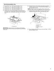
...the microwave oven (as shown), performance will be reattached to back of microwave oven with flat sides facing the back of "Wall Venting Installation Only." 5 Exhaust port IMPORTANT: If blower motor is not correctly oriented, the 2 screws removed in the top of microwave oven.... Damper plate B. Repeat Step 3 from "Wall Venting Installation Only." 2. Make sure damper plate tabs are inserted into microwave oven. A B C A. Slots 8. Rotate blower motor so that exhaust ports...
...the microwave oven (as shown), performance will be reattached to back of microwave oven with flat sides facing the back of "Wall Venting Installation Only." 5 Exhaust port IMPORTANT: If blower motor is not correctly oriented, the 2 screws removed in the top of microwave oven.... Damper plate B. Repeat Step 3 from "Wall Venting Installation Only." 2. Make sure damper plate tabs are inserted into microwave oven. A B C A. Slots 8. Rotate blower motor so that exhaust ports...
Installation Guide
Page 6
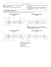
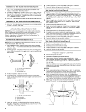
... A. Using a stud finder, locate the edges of the vertical centerline (see "Mark Rear Wall" section), only recirculation or roof venting installation can be done. Support tabs F. Cabinet opening vertical centerline C. Holes for lag screws E. Locate Wall Stud(s) NOTE: If no wall ...stud center. See illustrations in "Possible Wall Stud Configurations." Wall stud centerlines D. Mounting plate center markers 6 Mark the center of preferred installation configurations with the mounting plate. Wall Stud at One End Hole Figure 3 Wall Studs at End Holes Figure 2 B C C C...
... A. Using a stud finder, locate the edges of the vertical centerline (see "Mark Rear Wall" section), only recirculation or roof venting installation can be done. Support tabs F. Cabinet opening vertical centerline C. Holes for lag screws E. Locate Wall Stud(s) NOTE: If no wall ...stud center. See illustrations in "Possible Wall Stud Configurations." Wall stud centerlines D. Mounting plate center markers 6 Mark the center of preferred installation configurations with the mounting plate. Wall Stud at One End Hole Figure 3 Wall Studs at End Holes Figure 2 B C C C...
Installation Guide
Page 7
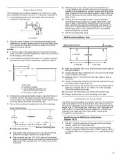
... "Locate Wall Stud(s)" section), align the mounting plate center markers to the wall stud centerline(s). If the end holes are 3 installation configurations. NOTES: ■ If the front edge of the upper cabinet is lower than the back edge, lower the cardboard template... is the venting cutout area. 13. Holding the mounting plate in place, find and clearly mark the vertical centerline of the upper cabinet. Wall Venting Installation Only Upper cabinet bottom ³⁄₈" (1 cm) 4" (10.2 cm) Centerline 6" (15.2 cm) 6" (15.2 cm) 8. Measure down from ...
... "Locate Wall Stud(s)" section), align the mounting plate center markers to the wall stud centerline(s). If the end holes are 3 installation configurations. NOTES: ■ If the front edge of the upper cabinet is lower than the back edge, lower the cardboard template... is the venting cutout area. 13. Holding the mounting plate in place, find and clearly mark the vertical centerline of the upper cabinet. Wall Venting Installation Only Upper cabinet bottom ³⁄₈" (1 cm) 4" (10.2 cm) Centerline 6" (15.2 cm) 6" (15.2 cm) 8. Measure down from ...
Installation Guide
Page 8
...round-head bolts and toggle nuts or 1/4 x 2" lag screws. C A 6. Leave enough space for the toggle nuts to the wall at the other end hole. If installing on a second wall stud, insert a lag screw into wall stud(s) in Rear Wall" section. 8 Upper-cabinet template D 10" (25.4 cm) F E 10" ... 1 & 2) NOTE: The mounting plate must be sure the "Rear Wall" arrows align to points "D" and "E" on at least 1 wall stud as well as installed) has a partial wall covering (for example, tile backsplash), be against the upper cabinet bottom. B A C A. 1/4-20 x 3" round-head bolt B. Start a...
...round-head bolts and toggle nuts or 1/4 x 2" lag screws. C A 6. Leave enough space for the toggle nuts to the wall at the other end hole. If installing on a second wall stud, insert a lag screw into wall stud(s) in Rear Wall" section. 8 Upper-cabinet template D 10" (25.4 cm) F E 10" ... 1 & 2) NOTE: The mounting plate must be sure the "Rear Wall" arrows align to points "D" and "E" on at least 1 wall stud as well as installed) has a partial wall covering (for example, tile backsplash), be against the upper cabinet bottom. B A C A. 1/4-20 x 3" round-head bolt B. Start a...
Installation Guide
Page 9
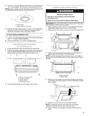
... out the rectangular area. Position the damper assembly on Upper Cabinet Template. 8. Handle the microwave oven gently. 1. Support tabs 4. Metal cabinet B. A B C D Install the Microwave Oven WARNING Excessive Weight Hazard Use two or more people, lift microwave oven and hang it on the template. Failure to move and... through the wall, make sure the damper assembly fits easily into the vent in the bottom of mounting plate. For Roof Venting Installation Only 7. Make sure the microwave oven door is the heavy side. Check that the damper blade hinge is for the power supply...
... out the rectangular area. Position the damper assembly on Upper Cabinet Template. 8. Handle the microwave oven gently. 1. Support tabs 4. Metal cabinet B. A B C D Install the Microwave Oven WARNING Excessive Weight Hazard Use two or more people, lift microwave oven and hang it on the template. Failure to move and... through the wall, make sure the damper assembly fits easily into the vent in the bottom of mounting plate. For Roof Venting Installation Only 7. Make sure the microwave oven door is the heavy side. Check that the damper blade hinge is for the power supply...
Installation Guide
Page 10
... can result in place, insert bolts through the cabinet cutout so that the long tab of the damper assembly slides under vent) Complete Installation 1. NOTE: The screw cannot be added. Raised tabs B. Tighten bolts until there is required, rotate microwave oven downward. Damper assembly ... Longer or shorter bolts are available at least one person holding it in death, fire, or electrical shock. 2. Bolts For Roof Venting Installation Only 1. Then secure with at most hardware stores. ■ Overtightening bolts may warp the top of the damper plate. Long tab F....
... can result in place, insert bolts through the cabinet cutout so that the long tab of the damper assembly slides under vent) Complete Installation 1. NOTE: The screw cannot be added. Raised tabs B. Tighten bolts until there is required, rotate microwave oven downward. Damper assembly ... Longer or shorter bolts are available at least one person holding it in death, fire, or electrical shock. 2. Bolts For Roof Venting Installation Only 1. Then secure with at most hardware stores. ■ Overtightening bolts may warp the top of the damper plate. Long tab F....
Installation Guide
Page 11
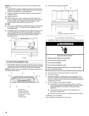
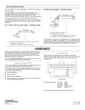
... between the top of the microwave oven and the rectangular to 15.2 cm = 1.5 m) B. NOTES: ■ Vent materials needed for installation are for architectural designer and builder/contractor reference only. Do not vent exhaust air into concealed spaces, such as spaces within the wall for ... optimal hood performance If venting through the roof, and rectangular to open freely and fully. See the examples in the vent system ■ using recirculation installation. Rectangular to round transition piece: 3¹⁄₄" x 10" to 6" = 5 ft (8.3 x 25.4 cm to round transition piece so ...
... between the top of the microwave oven and the rectangular to 15.2 cm = 1.5 m) B. NOTES: ■ Vent materials needed for installation are for architectural designer and builder/contractor reference only. Do not vent exhaust air into concealed spaces, such as spaces within the wall for ... optimal hood performance If venting through the roof, and rectangular to open freely and fully. See the examples in the vent system ■ using recirculation installation. Rectangular to round transition piece: 3¹⁄₄" x 10" to 6" = 5 ft (8.3 x 25.4 cm to round transition piece so ...
Installation Guide
Page 12
... frame of the microwave oven. W10247296B SP PN W10345003B © 2010. See "Recommended Standard Fittings" section for details. For best performance, use when installing this microwave oven in a 36" (91.4 cm) or 42" (106.7 cm) wide opening , behind the door. ■ Damper Assembly &#... and Parts" section) A A. In addition, a rectangular 3" (7.6 cm) extension vent between the damper assembly and rectangular to round transition piece must be installed to round transition piece must not exceed the equivalent of 140 ft (42.7 m) for either type of vent. Two 90° elbows = 20 ft ...
... frame of the microwave oven. W10247296B SP PN W10345003B © 2010. See "Recommended Standard Fittings" section for details. For best performance, use when installing this microwave oven in a 36" (91.4 cm) or 42" (106.7 cm) wide opening , behind the door. ■ Damper Assembly &#... and Parts" section) A A. In addition, a rectangular 3" (7.6 cm) extension vent between the damper assembly and rectangular to round transition piece must be installed to round transition piece must not exceed the equivalent of 140 ft (42.7 m) for either type of vent. Two 90° elbows = 20 ft ...

Dimension Guide
Page 1
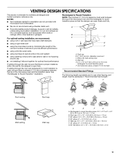
... m) C. 2 ft (0.6 m) + 6 ft (1.8 m) straight = 8 ft (2.4 m) A. 2" x 4" wall stud B. Roof cap B. 6" (15.2 cm) min. For complete details, see Installation our products, we reserve the right to improve Dimensions are for each vent piece used . Instructions packed with a fuse or circuit breaker. Specifications subject to... Round Transition for 66" (167.6 cm) installation height. For best performance, use no more than three 90° elbows. Rectangular to round transition piece: 3 " x 10"...
... m) C. 2 ft (0.6 m) + 6 ft (1.8 m) straight = 8 ft (2.4 m) A. 2" x 4" wall stud B. Roof cap B. 6" (15.2 cm) min. For complete details, see Installation our products, we reserve the right to improve Dimensions are for each vent piece used . Instructions packed with a fuse or circuit breaker. Specifications subject to... Round Transition for 66" (167.6 cm) installation height. For best performance, use no more than three 90° elbows. Rectangular to round transition piece: 3 " x 10"...

Warranty Information
Page 1
...door. Have your major appliance. Damage resulting from accident, alteration, misuse, abuse, fire, flood, acts of God, improper installation, installation not in accordance with electrical or plumbing codes, or use your correspondence. Repairs to parts or systems resulting from unauthorized modifications... made to view FAQs (Frequently Asked Questions), visit www.kitchenaid.com. KITCHENAID SHALL NOT BE LIABLE FOR INCIDENTAL OR CONSEQUENTIAL DAMAGES. THIS WARRANTY GIVES YOU SPECIFIC LEGAL RIGHTS, AND YOU MAY...
...door. Have your major appliance. Damage resulting from accident, alteration, misuse, abuse, fire, flood, acts of God, improper installation, installation not in accordance with electrical or plumbing codes, or use your correspondence. Repairs to parts or systems resulting from unauthorized modifications... made to view FAQs (Frequently Asked Questions), visit www.kitchenaid.com. KITCHENAID SHALL NOT BE LIABLE FOR INCIDENTAL OR CONSEQUENTIAL DAMAGES. THIS WARRANTY GIVES YOU SPECIFIC LEGAL RIGHTS, AND YOU MAY...

